The ST kit connects the control port to the piston chamber. The PKL
equipped with the ST kit strikes as long as there is compressed air.
• For PKL 190 / 450 proceed as follows:
- Mount the ST screw fitting (after the NBS).
- A 3/2-way valve with air supply is necessary.
• For PKL 740 proceed as follows:
- Replace the silencer with the compressed air connection.
- Only one air supply is necessary.
• Order the PKL 2100 directly with the ST control.
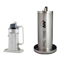
• For PKL 5000 proceed as follows:
- Mount the control valve of the ST control to the PKL.
- The control valve is connected internally to the piston chamber, the
ST control is integrated in the PKL.
For detailed information, please refer to the Assembly Instructions for the
ST kit.
For all installations, use a ball valve to shut off the main line and a mainte-
nance unit.
The maintenance unit should comprise a filter, a regulator and a mist lubri-
cator (see page 7; "Drive medium").
Connect the PKL with the pneumatic hose according to the following de-
picted pneumatic circuit diagrams.
Define the impact sequence of the PKL with an electrical control, e.g. the
Netter Electronic Timer AP 117.
Recommended cross-sections for control lines, control valves and main air
supply: DN 6 × 1
To connect the control valve to the PKL:
• DN 6 should be used and
• a length of 15 m should not be exceeded.
For simultaneous operation of several PKL
• larger cross-sections are to be provided for the main line up to distribu-
tion to the individual PKL.
• the total length of the compressed air supplies is max. 50 m.
 Loading...