Digicom/RedCARE Installation
Astandalonedigitalcommunicator,RedCARESTU
or Paknet interface card can be connected to the
control panel using the following connections:
Digicom Outputs 1 to 8
These are the programmable digicom output
connections. They are normally at +12V and
switch to 0V when active. The outputs can be
inverted so that they switch from 0V to +12V when
active (see System Configuration on page 31).
Each output willsource5mAinthe+12Vcondition
and sink 100mA in the 0V condition.
+DC POWER
This provides the +12V power to the digicom. This
output is un-fused and therefore should only be
used if the digicom is fitted inside the control
panel. The 0V supply for the digicom/STU can be
picked up from any of the auxiliary 0V terminals.
LINE FLT
When this input is switched to +12V, a “Line Fault”
condition is generated. A “Line Fault” condition In
the unset mode will cause a “Chime” type tone to
be generated every minute, which can be
silenced by entering any valid passcode. A “Line
Fault” condition In the set mode will cancel the
“Bell Delay”.
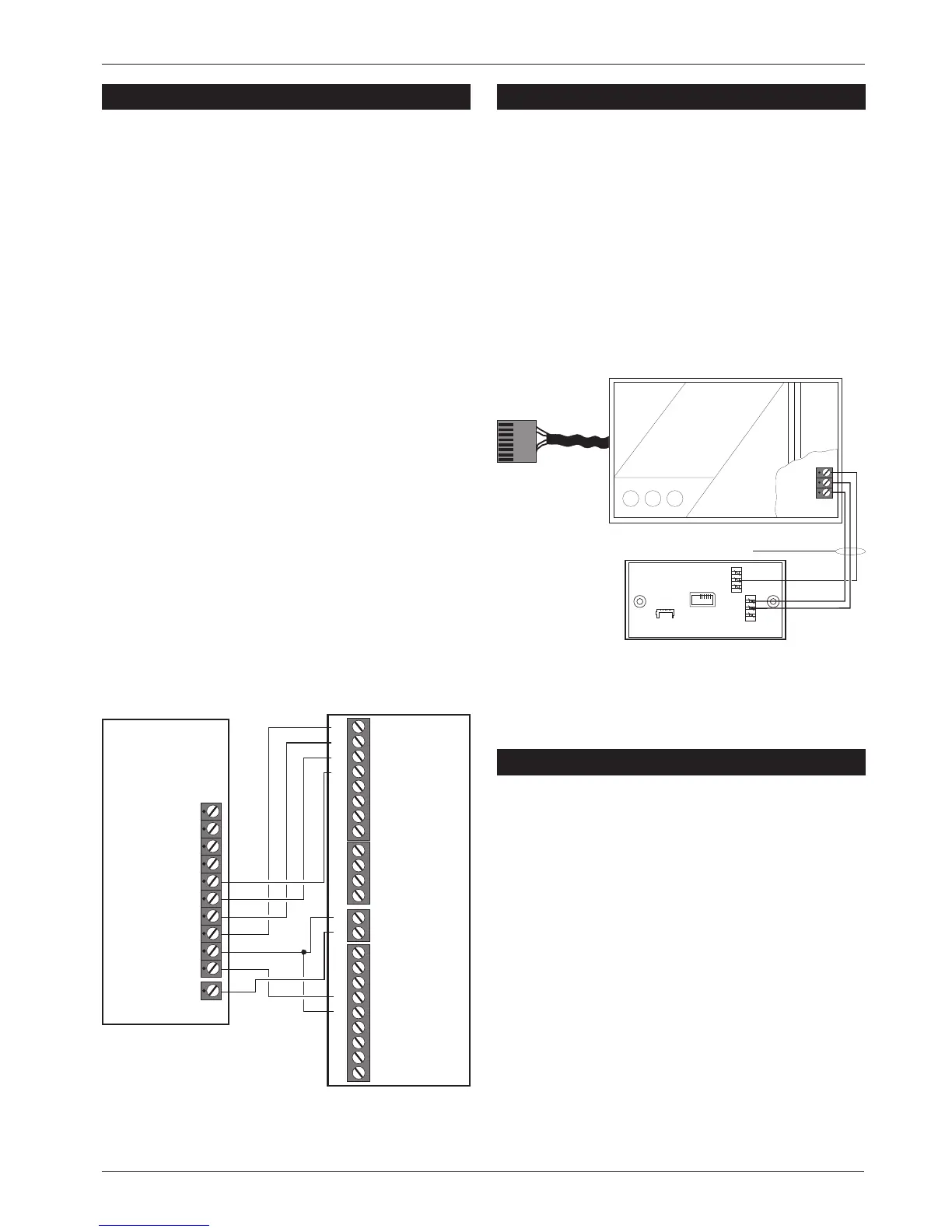
Plug-on Digicom Installation
A plug-on digital communicator DC54 or DC58
may be fitted inside the control panel to allow
alarm status information to be transferred to a
dedicated centralstation. The unitshould be fitted
in accordance with the installation instructions
supplied with it and connected to the control
panel plug DIGI-MODEM (JP3) using the lead
provided with the unit, see Figure 21. The NVM
within the digicom can be programmed via the
control panel, see page 48.
Plug-on digi-Modem Installation
A plug-on digi-modem DC58M may be fitted
inside the control panel to allow remote
interrogation and programming via a personal
computer (PC). It will also function as a standard
digicom (if required). The unit should be fitted in
accordance with the installation instructions
supplied with it and connected to the control
panel plug DIGI-MODEM using the lead provided
with the DC58M. The NVM within the digi-modem
can be programmed via the control panel, see
page 48. The modem data is also programmed
via the control panel.
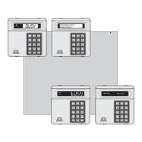
Control
Panel
3GSTU
1
1
+DC POWER
Program
As:-
Open (060)
Alarm (005)
PA (006)
Fire (007)
LINE FLT
AUX 0V
2
2
3
3
4
4
5
TB1
Channel Inputs are
Programmed as
Positive Removed
TB2
TB3
TB4
Control
Line
Fault RPS
5
6
6
7
7
0V
NO
NO
NO
NC
NC
NC
8
8
C C
C
A+ A+ A+ A+ V+
Figure 20 3GSTU RedCARE Connections
Connect to JP7
DIGI-MODEM
Plug-on digicom / digi-modem
A
B
BC
B.T. master jack ( Type NTE5
user accessible connections )
A(5) = White / Blue ring
BC(3) = Blue / White ring
B(2) = Orange / White ring
Telephone cable
(Type 1/0.5mm CW1308)
6