10 DISMANTLING AND ASSEMBLY
OF THE ROTATING PARTS
PAGE
10.2
issued: 20.04.2017 Revision: 7
text no.
10318-2/2
copy to:
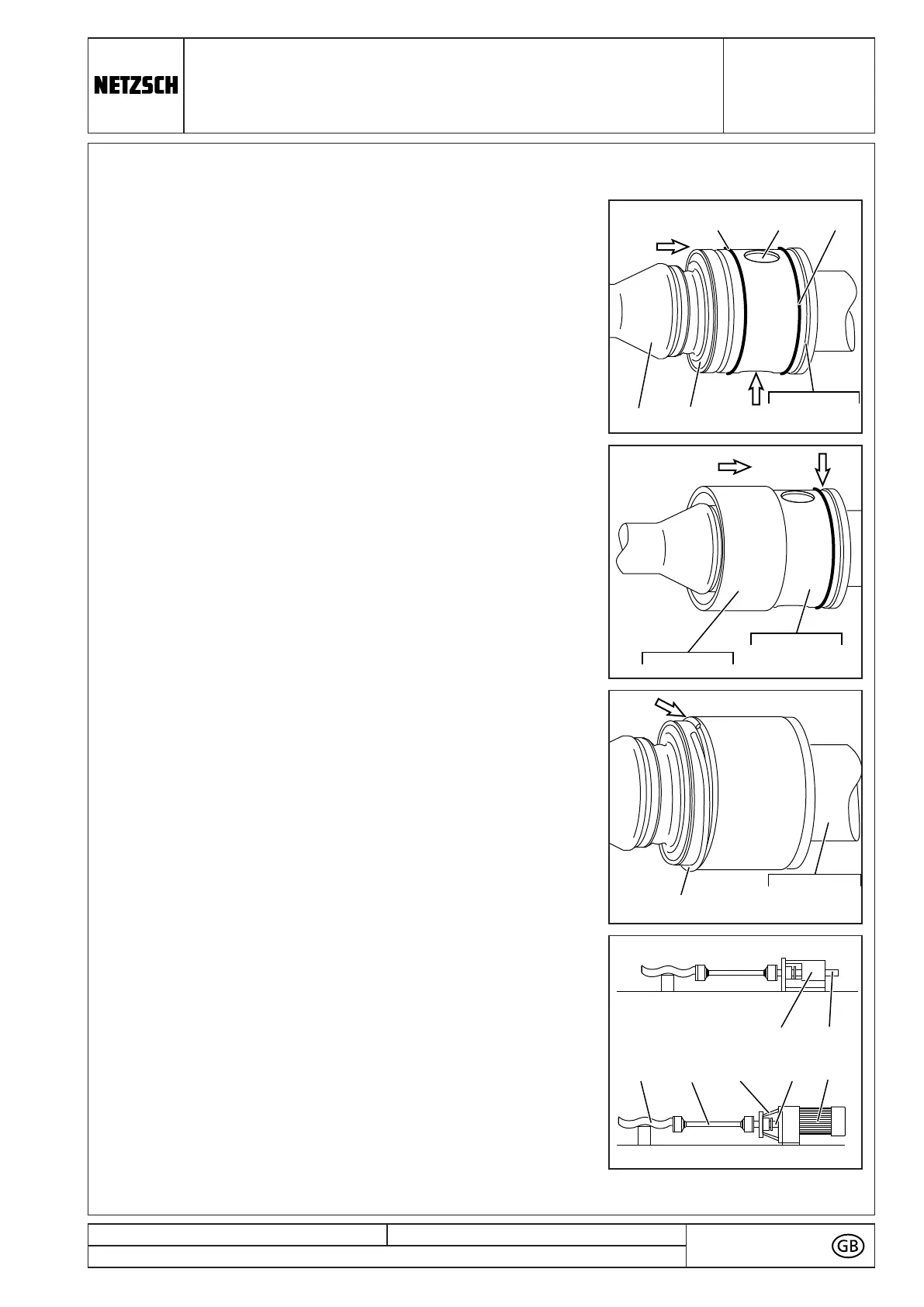
■ Remove the hose.
■ Push the pin (5075) entirely into the bore of head of
rotor (1999), connecting shaft (1050) or connection
sleeve (5055/5056) and retain in place.
■ Only now, press the SM-pin joint seal (8235) into the
bore of head of rotor (1999), connecting shaft (1050)
or connection sleeve (5055/5056) and push up to the
shoulder. In doing so the SM-pin joint seal (8235)
should be slightly bulbous around the outer surface.
■ Wipe off overflow oil. Use this oil for lubricating the
O-rings (8060).
8235
8060 5075
1998
1050, 1999
5055, 5056
8060
■ Slip the sleeve (5110/5115), with its chamfering (A)
forward, on to the head of rotor (1999), connecting
shaft (1050) or connection sleeve (5055/5056) and
push up to the shoulder.
5110,5115
1050, 1999
5055, 5056
■ Place the circlip (5065) into its groove on the rotor
head (1999), connecting shaft (1050) or connection
sleeve (5055/5056) and carefully snap in place all
around.
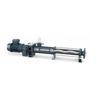
The drive shaft (1005)/the connecting shaft (1050)
(with or without connection sleeve (5055/5056)), the
coupling rod (1998) and the rotor (1999) are now
joined by means of the two pin joints.
The pump housing (2010), the stator (3005) and the
end connection (2005) may now be fitted.
(→ chapter 9).
0085 A1998 10501999
0005 1005
IPP - EN - EN_10318_20170420/3 - D8411276 - 4300003998 - 000100 - NPS - 00229929 N 2018-02-21 19:03:25
73