10 DISMANTLING AND ASSEMBLY
OF THE ROTATING PARTS
PAGE
10.1R
text no.
R 10318-1/2
issued: 20.04.2017 Revision: 7
copy to:
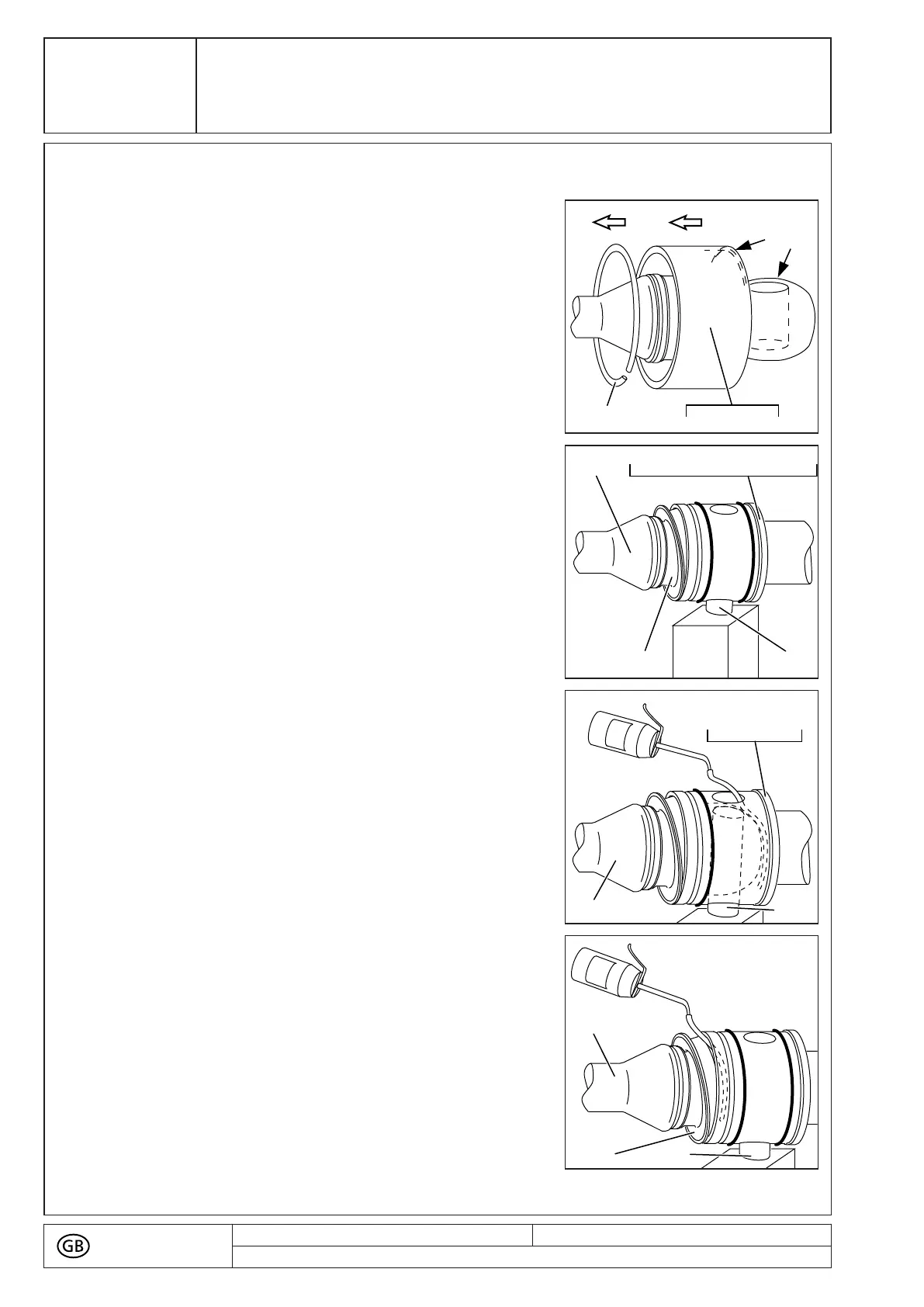
■ Slip the circlip (5065) on to the coupling rod (1998).
■ Slide the safety sleeve (5110/5115) on to coupling
rod (1998) so the inside diameter of chamfering (A)
is being placed towards the coupling rod (1998)
extension.
Chamfering (A) will later on ease the installation over
the O-rings (8060).
■ Orient the head of coupling rod (1998) until it is in
vertical position for the bore (B) for the pin (5075).
■ Slide the coupling rod (1998) with SM-pin joint seal
(8235) into the bore of rotor (1999), connecting shaft
(1050) or connection sleeve (5055/5056).
■ Insert the pin (5075) from below and push up to the
upper edge of coupling rod (1998).
■ Support the pin (5075) against dropping out.
■ Slide the SM-pin joint seal (8235) into the rotor
(1999), connecting shaft (1050) or connection sleeve
(5055/5056) only from below, and in a slightly
slanted position.
1998
50758235
1050, 1999, 5055, 5056
■ For lubrication, use an oil can which should be fitted
with a thin plastic hose having an outside diameter
of not more than 4 mm.
■ Insert this hose into the upper oil port opening in the
rotor (1999), connecting shaft (1050) or connection
sleeve (5055/5056).
■ Slide the hose end past the coupling rod (1998) all
the way down to the bottom section of the rotor head
(1999) or connecting shaft (1050) or connection
sleeve (5055/5056).
■ Slowly fill with lubricating oil up to the filling port.
50751998
1050, 1999
5055, 5056
■ Pull the hose out.
■ Insert the hose end through the small gap on the
topside of SM-pin joint seal (8235) and guide it down
to the bottom of the hollow space between coupling
rod (1998) and SMpin joint seal (8235).
■ Slowly fill with lubricating oil up to the gap.
IPP - EN - EN_10318_20170420/2 - D8411276 - 4300003998 - 000100 - NPS - 00229929 N 2018-02-21 19:03:25
72