11
Operating Manual Gearbox
Mounting
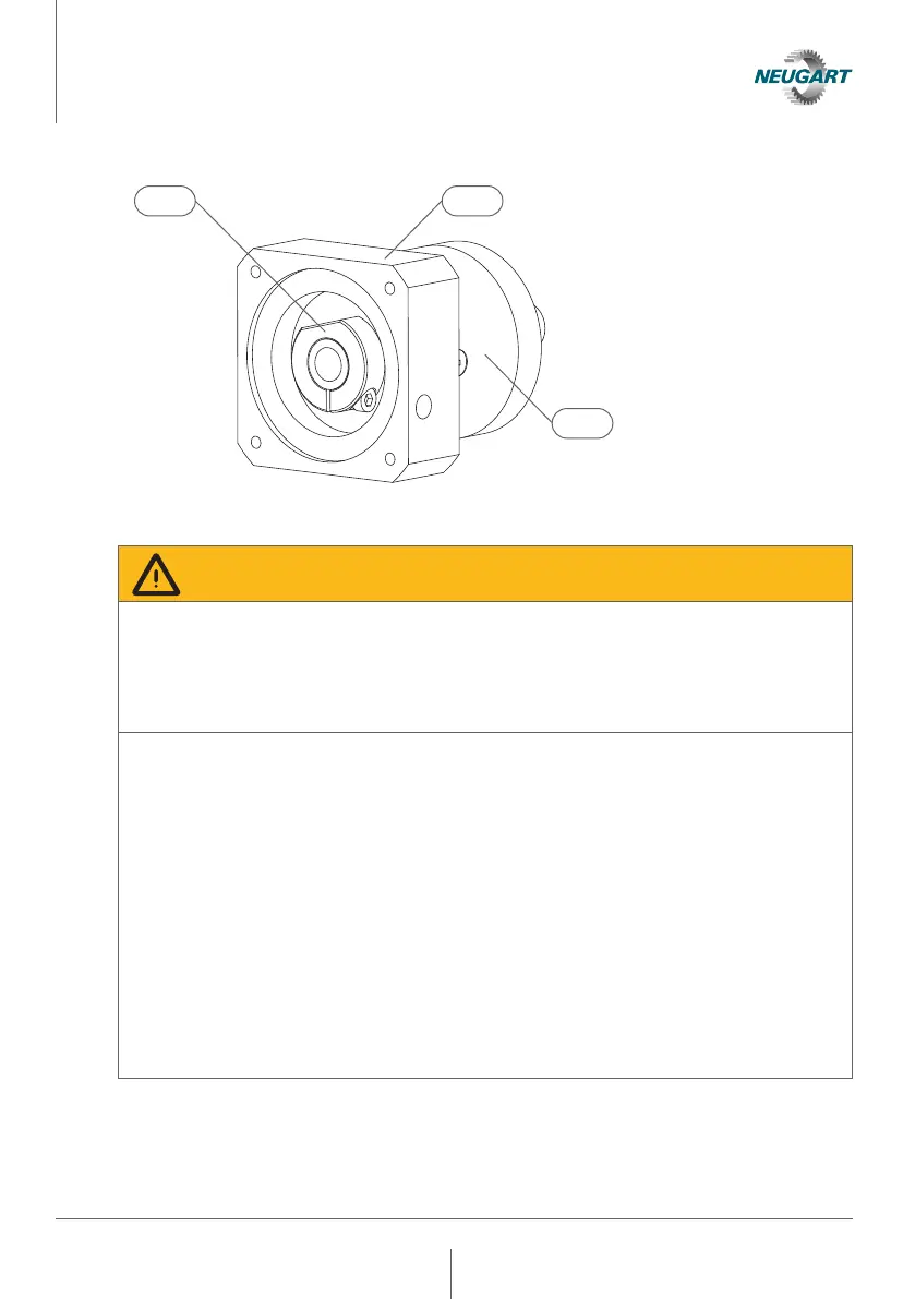
1 Clamping System
2 Drive flange
3 Gearbox housing
4.1.1 Attaching the motor
Warning!
Due to its weight, incorrect mounting or in the event of unacceptable deviation from
radial run-out and axial run-out tolerances., the motor can cause a gear compo-
nent or a connecting element to break. Among other things, this can result in a
loss of position in the power train, uncontrolled rotation or a blocking of the output
shaft.
• The permissible motor weight or bending moment given in the technical specifi-
cation must be observed.
• The mounting instructions for motor mounting must be observed.
• Carefully clean the component surfaces to be used for non-positive connection
and remove all residues.
• Radial run-out and axial run-out tolerances must be ensured when mounting
a motor based on the values of the technical specification and the measuring
method described in 4.1.3.1 to 4.1.3.5.
• Observe the bolt tightening torques of the motor manufacturer when fastening
the motor.
• Select a suitable torque tool with a minimum accuracy to DIN EN ISO 6789-1
Type II A to ensure the required tightening torque.
• The bolts must be secured against self-loosening through use of a threadlocker
(e.g. Loctite 245).
21
3
 Loading...