The LB1005 High-Speed Servo Controller is a high-performance, standalone instrument designed for achieving stable feedback control in various applications, particularly those requiring high-bandwidth filtering to stabilize laser system parameters like intensity and frequency.
Function Description:
The primary function of the LB1005 is to condition an input signal from a detector and provide an output signal to a transducer that controls a system parameter. This output control signal forces the system parameter to a desired value, compensating for external disturbances such as thermal fluctuations or mechanical noise. The device generates an error signal from the detector signal, filters it, and then outputs a control signal to adjust the transducer.
The LB1005's signal architecture comprises three main stages:
- Input Section: This stage features a differential amplifier with an adjustable voltage offset. It can subtract common-mode voltages ranging from ±10V. Error signals exceeding ±330 mV saturate the filter amplifier.
- Filter Section: This section converts the error signal into a control signal using a proportional-integral (P-I) filter. Front panel controls allow adjustment of the overall loop gain, the P-I corner frequency, and an optional low-frequency gain limit. A toggle switch enables/disables the P-I filter output for acquiring lock. A TTL input can also be used to disable the error signal input and hold the P-I filter output at its current value.
- Output Section: This is a summing amplifier that combines the P-I control signal with auxiliary signals, such as external sweep and modulation inputs. The output voltage range of this section can be limited by rear panel trimpot adjustments.
Important Technical Specifications:
- Signal bandwidth (-3 dB): 10-18 MHz
- Propagation delay: 50 ns (<10 MHz)
- Input Section:
- Input impedance (A, -B): 1 MΩ
- Input voltage (A, -B): ±10 V
- Input voltage noise density (A, -B): 10 nV Hz⁻¹ᐟ² (>1 kHz)
- Common mode rejection ratio (A-B): 60 dB (<10 kHz)
- Input offset voltage: ±10 V (Range selectable)
- Error monitor output impedance: 50 Ω
- Error monitor bandwidth: 10 MHz
- Error monitor gain: 1 V/V
- Error monitor output voltage: ±11 V
- Filter Section (P-I controller):
- Gain range: -40 to +40 dB (Log scale, continuous adjust)
- P-I corner frequency range: 10 Hz to 1 MHz (Half-log steps)
- Low frequency gain limit range: 20 to 90 dB (10-dB steps)
- Filter parameter accuracy: 10 %
- Aux output impedance: 50 Ω
- Aux output voltage: ±11 V
- Integrator hold “on” level: 2.4 V (TTL)
- Integrator hold “off” level: 0.8 V (TTL)
- Output Section (Summing amplifier):
- Output voltage: ±11 V (Unclamped), 0-10 V (Positive limit), -10-0 V (Negative limit)
- Output impedance: 50 Ω
- Output current: ±20 mA
- Sweep input impedance: 1 MΩ
- Sweep input bandwidth: 10 kHz
- Sweep input voltage: ±10 V
- Sweep span attenuation: 0-100 %
- Sweep center bias voltage: ±10 V
- Modulation input impedance (1, 2): 1 MΩ
- Modulation input bandwidth (1, 2): 1 MHz (<1 Vp-p)
- Modulation input (1, 2): ±10 V
- Modulation attenuation (1, 2): 0-100 %
A.2. Environmental Specifications:
- Operating temperature: 10-40 °C
- Transportation/storage temperature: -40-80 °C
- Maximum relative humidity: 80 %
- Maximum operating altitude: 2000 m
- Instrument weight: 3 kg
A.3. Electrical Specifications:
- Use type: Indoor Use Only
- Protection: Ordinary Protection (Not protected against ingress of moisture)
- Equipment class: Class I (Grounded Type)
- Electrical rating: 100/120/220/230-240V~ 0.5/0.5/0.25/0.25A 50/60Hz
- Voltage tolerance: ±10% of nominal supply voltage
- Fuse rating: 250V 0.5A T or 250V 0.25A T (Metric sizing only: 5mm x 20mm)
- Ambient pollution: Pollution Degree 2
- Transient overvoltages: Installation Category II
Usage Features:
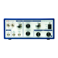
Front Panel Connections & Controls:
- A, -B Inputs (1): BNC inputs for the error signal, 1 MΩ impedance, ±10 V range. Auto-terminate for single-ended operation.
- Input Offset (2): 10-turn locking knob for adding/subtracting a stable offset voltage (±1 V or ±10 V range, selectable via rear panel switch).
- Error Monitor (3): BNC output for monitoring the error signal (unity gain, ±10 V nominal range, 10 MHz bandwidth).
- Sweep In (4): BNC input for adding a low-frequency periodic sweep signal to the output (1 MΩ impedance, ±10 V range).
- Output (5): BNC output for the control signal (50 Ω impedance, ±20 mA drive current).
- Sweep Center (Output Offset) (6): 10-turn knob to adjust the offset voltage of the output signal.
- Sweep Span (7): 1-turn knob to control the attenuation (amplitude) of the Sweep In signal (0 to unity gain).
- P-I Corner (8): 12-position switch to set the proportional-integral corner frequency.
- LF Gain Limit (9): 9-position switch to control the low frequency gain limit (LFGL) of the loop filter (active in LFGL mode).
- Gain (10): 10-turn knob for continuous adjustment of the overall feedback gain (-40 dB to +40 dB).
- Acquire switch (11): 3-position switch for acquiring lock:
- Lock Off: Integrator reset, no control signal to output.
- LFGL: P-I filter enabled with low frequency gain limit.
- Lock On: P-I filter enabled with full integrator, low frequency gain limit disabled.
- LED lock indicator (12): Indicates operating status:
- Unlighted: Power off.
- Green (LOCKED): Acquire switch in LFGL or Lock On, error signal within ±0.33 V, output signal not within 10% of voltage limits.
- Red (UNLOCKED): All other conditions.
Rear Panel Connections & Controls:
- Power switch (1): On/Off switch for AC mains power.
- Power entry module (2): Receptacle for AC power cord, configurable for 100, 120, 220, 230-240 VAC.
- Input Offset Range (3): 3-position switch for Input Offset knob range (Off, ±1 V, ±10 V).
- Output Voltage Limits (4): 15-turn trimpots to set positive and negative output voltage rails.
- Mod 1 Input, Mod 2 Input (5): BNC inputs for external modulation signals (±10V, 1 MΩ impedance, 1 MHz bandwidth).
- Attn 1, Attn 2 (6): 15-turn trimpots to attenuate corresponding modulation inputs (off to unity gain).
- Aux Output (7): BNC output of the P-I filter section, bypassing summing amplifier (±10 V range, 50 Ω impedance).
- Int Hold Input (8): TTL logic input to hold integrator output at its current value (low for normal operation, high to hold).
Typical Operation Steps:
- Reset integrator: Set Acquire switch to Lock Off.
- Find the locking point: Enable sweep (Sweep Span knob), adjust Sweep Center to position the lock feature, and use Input Offset to align the desired lock point with zero voltage on the Error Monitor.
- Acquire lock: Switch Acquire to LFGL (for limited DC gain) or Lock On (for full integrator gain).
- Turn off sweep: After acquiring lock, set Sweep Span knob to Off.
- Adjust filter: Tune P-I Corner frequency for stability and optimize Gain by increasing it until oscillation is observed on the Error Monitor, then reducing it slightly.
Setting Output Voltage Limits:
- Turn Sweep Center fully clockwise (for positive limit) or counter-clockwise (for negative limit).
- Monitor Output voltage and adjust the corresponding rear panel trimpot (+ or -) until the desired limit is reached.
- Warning: Ensure the voltage difference between positive and negative limits is greater than 2 V.
Using the Integrator Hold:
A TTL digital "high" signal applied to the rear panel Int Hold BNC connector disables the error signal input to the P-I filter, holding the integrator output at its current value. This is useful for managing large perturbations that could cause the system to lose lock, allowing the control voltage to be maintained at a safe, fixed value until the disturbance recedes.
Two independent modulation inputs (Mod 1, Mod 2) are available for summing external signals (e.g., modulation frequencies for lock-in detection, feedforward correction) into the output. Rear panel trimpots (Attn 1, Attn 2) control their attenuation. Unused modulation inputs should have their attenuation trimpots turned fully counter-clockwise to prevent unwanted signal pickup.
Maintenance Features:
- Maintenance-free design: The LB1005 is designed to be maintenance-free with no user-serviceable parts inside. No further calibrations are necessary over the product's lifetime.
- Cleaning: The instrument case can be safely cleaned with a slightly moistened cloth soaked in water or isopropyl alcohol.
- Service and Repair:
- Contact New Focus customer service for service, repair, calibration, or replacement.
- Obtain a Return Merchandise Authorization (RMA) before returning any unit.
- Pack the unit in original shipping material (if possible) with at least 1 inch of compressible packing material, including an ownership tag and a detailed defect description.
- Bookham will return the equipment with a repair report. A test set-up fee may apply if the equipment is within specifications.
- Shipping damage is not covered by warranty; shipping insurance is recommended.
Warranty:
Bookham warrants the LB1005 to be free of material and workmanship defects for one year from the date of original shipment. This warranty is in lieu of all other guarantees, expressed or implied. Bookham's liability is limited to the cost of correcting defects. The warranty does not cover defects caused by abuse, accident, modifications, Acts of God, or use for unintended purposes. The LB1005 should only be used as specified by the manufacturer.