LB1005 Operating Manual Introduction
Bookham Revision 1 3
Front Panel Connections & Controls
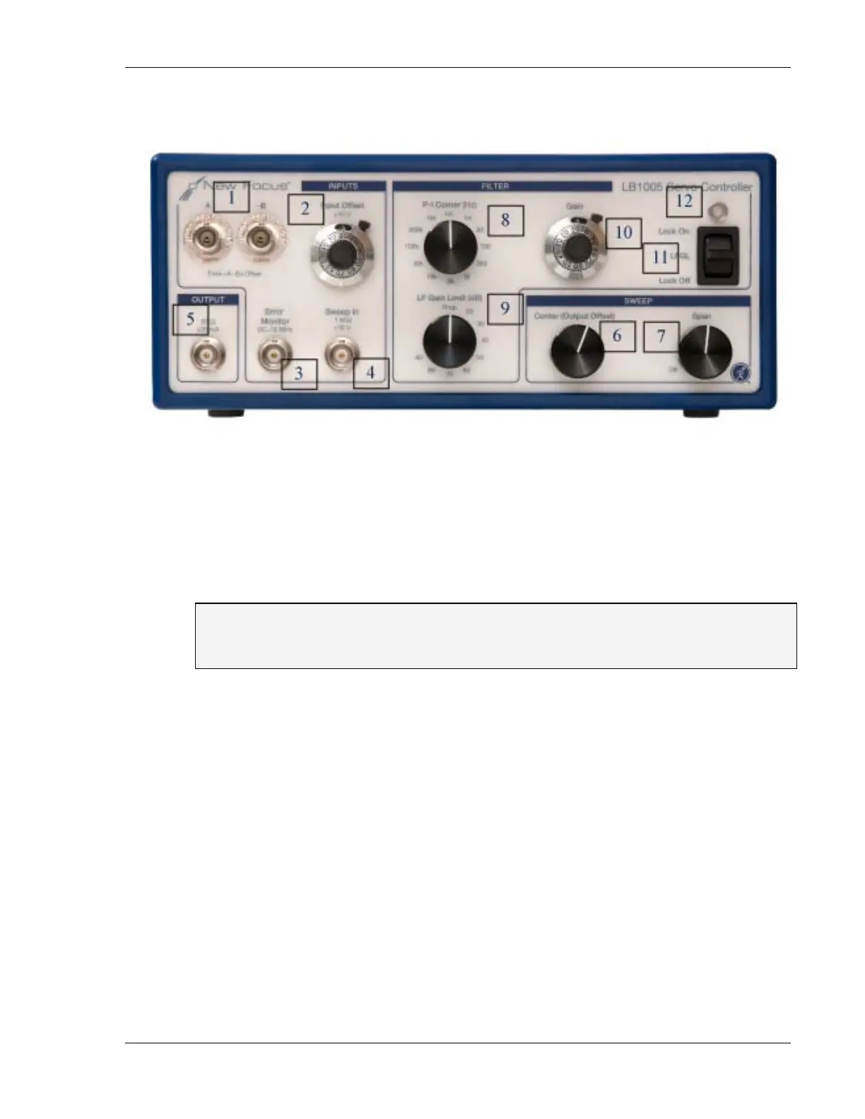
Figure 1: LB1005 Front Panel
1. A, -B: The error signal is generated from the voltage difference of these BNC
inputs. Both voltage channels have 1-MΩ input impedance and an input
voltage range of ±10 V. For single-ended operation, these BNC connectors
auto-terminate upon disconnection of cables.
Warning: For proper operation, cables attached to either of these inputs must be
driven with a voltage source or terminate into a low impedance. Make sure that any
attached BNC cable connectors are fully inserted and fastened to the panel connector.
2. Input Offset: This 10-turn locking knob controls a stable offset voltage that
can be added or subtracted from the voltage difference of the A and –B
inputs. This offset can be adjusted over a range of either ±1 V or ±10 V,
selected by the rear panel Input Offset Range switch. The Input Offset can
also be disabled. The offset voltage corresponds linearly to the dial readout:
V
Offset
= (0.2n −1) ×V
MaxRange
, where n is the number of turns read from the dial
indicator. For example, a dial value of n = 5.00 indicates a (near) zero offset
voltage.
3. Error Monitor: This BNC output connector is a voltage monitor for the error
signal generated by the input difference amplifier. The DC-coupled error
monitor has unity gain with a nominal output voltage range of ±10 V and a
bandwidth of 10 MHz.
4. Sweep In: This BNC input allows a low frequency periodic sweep signal to
be added to the output of the LB1005. The input impedance is 1 M
Ω and the