LB1005 Operating Manual Introduction
Bookham Revision 1 5
12. LED lock indicator: This LED light indicates the operating status of the
LB1005. Table 3 shows the correspondence of the LED color to the operating
conditions of the LB1005.
Table 3: LED Lock Indicator
LED Color Condition
Unlighted OFF: LB1005 is either disconnected from the AC mains supply, or
the rear panel power switch is in Off position (0).
Green
LOCKED:
Acquire switch is placed in either LFGL or Lock On position,
AND
Error signal voltage is within ±0.33 V.
AND
Output signal voltage is NOT within 10% (scaled to full voltage range)
of either the positive or negative output voltage limits.
Red UNLOCKED: All remaining operating conditions.
Rear Panel Connections & Controls
12
345
6
78 5
6
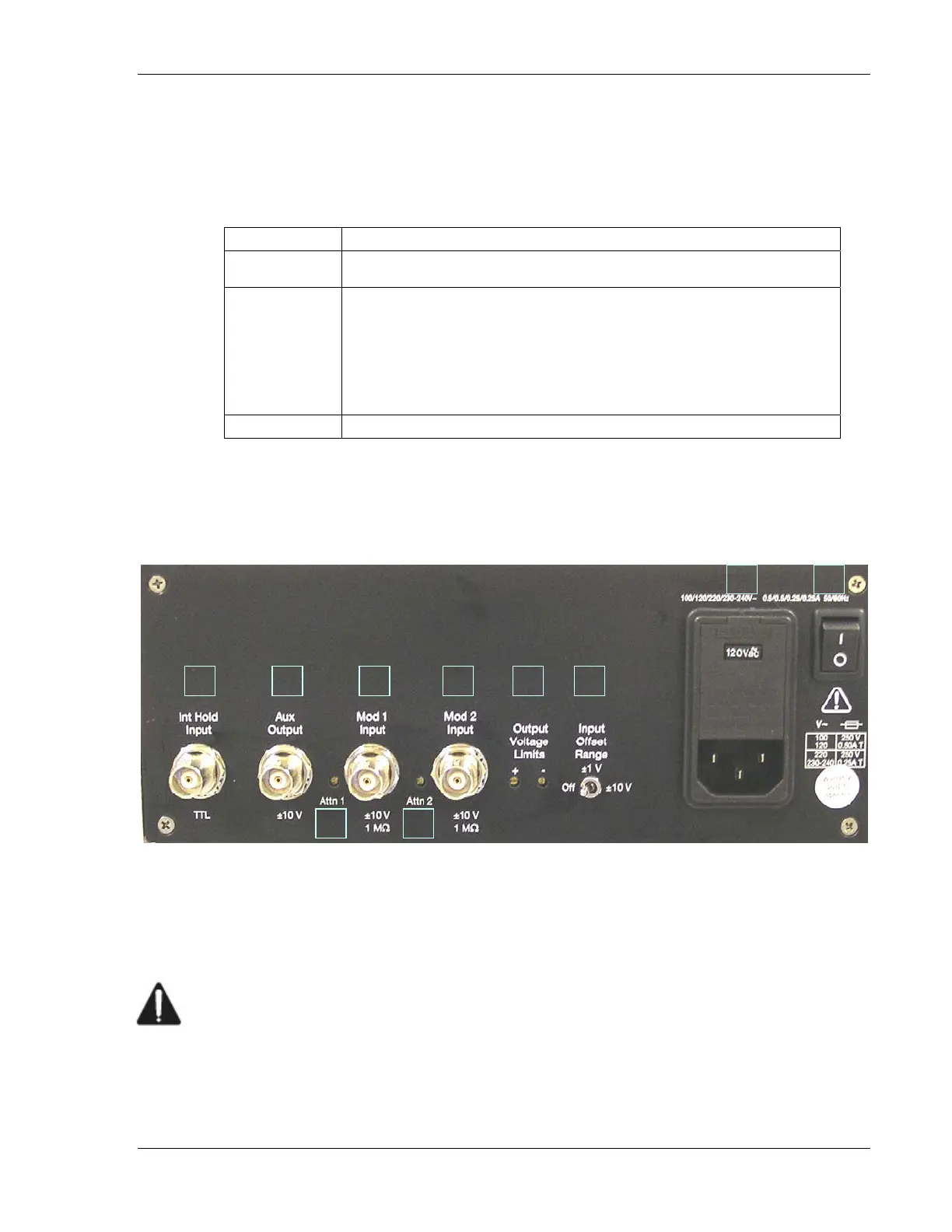
Figure 2: LB1005 Rear Panel
1. Power switch: This switch is pushed up to | position to turn on AC mains
power to LB1005.
2. Power entry module: The AC power cord must be connected between this
instrument receptacle and a properly grounded mains receptacle. The
LB1005 can be configured to operate with the following AC mains voltages:
100, 120, 220, and 230-240 VAC. Please carefully read the preceding section
Electrical Fuse & Voltage Selection for instructions on installing the proper fuses
and setting the correct AC supply voltage.