Introduction LB1005 Operating Manual
4 Revision 1 Bookham
input voltage range is ±10 V. See Sweep Center and Sweep Span controls
discussed below for more details.
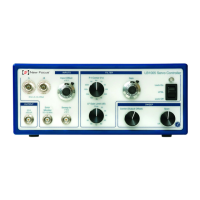
5. Output: This BNC output is the control signal from the proportional-integral
(P-I) filter, summed with the sweep and modulation signals. This output has
an impedance of 50 Ω and a drive current of ±20 mA.
6. Sweep Center (Output Offset): This 10-turn knob adjusts the offset voltage
of the signal from Output. The offset voltage can be adjusted from the
negative voltage limit (fully counter clockwise) to the positive voltage limit
(fully clockwise). See the section Setting Output Voltage Limits in Chapter 3 for
more details on setting the output voltage limits.
7. Sweep Span: This 1-turn knob controls the attenuation of the Sweep In
signal. Attenuation is near linear from zero (Off, fully counter-clockwise) to
unity gain (fully clockwise). This knob is used to adjust the amplitude of the
sweep input signal.
8. P-I Corner: This 12-position switch sets the proportional-integral (P-I) corner
frequency of the filter. See the section Filter Transfer Functions in Chapter 3
for details.
9. LF Gain Limit: This 9-position switch controls the low frequency gain limit
(LFGL) of the loop filter. This knob is only active when the Acquire switch is
in LFGL mode. See the section Filter Transfer Functions in Chapter 3 for
details.
10. Gain: This 10-turn knob continuously controls the overall feedback gain of
the loop filter from -40 dB (fully counter clockwise) to +40 dB (fully
clockwise). Gains from -30 dB to +30 dB have a dial indicator reading that is
near linear from indices n = 2 to 8 (~10 dB/turn).
11. Acquire switch: This 3-position switch is used to acquire lock. Table 2 shows
the function for each switch position.
Table 2: Functions for Acquire Switch
Position Function
Lock Off Integrator is reset. No control signal is summed into output signal.
LFGL
P-I filter is enabled with a low frequency gain limit determined by LF Gain
Limit switch. See the section Filter Transfer Functions in Chapter 3.
Lock On P-I filter is enabled with full integrator. Low frequency gain limit is disabled.