LB1005 Operating Manual Detailed Operation
Bookham Revision 1 13
Chapter 3 : Detailed Operation
Signal Architecture
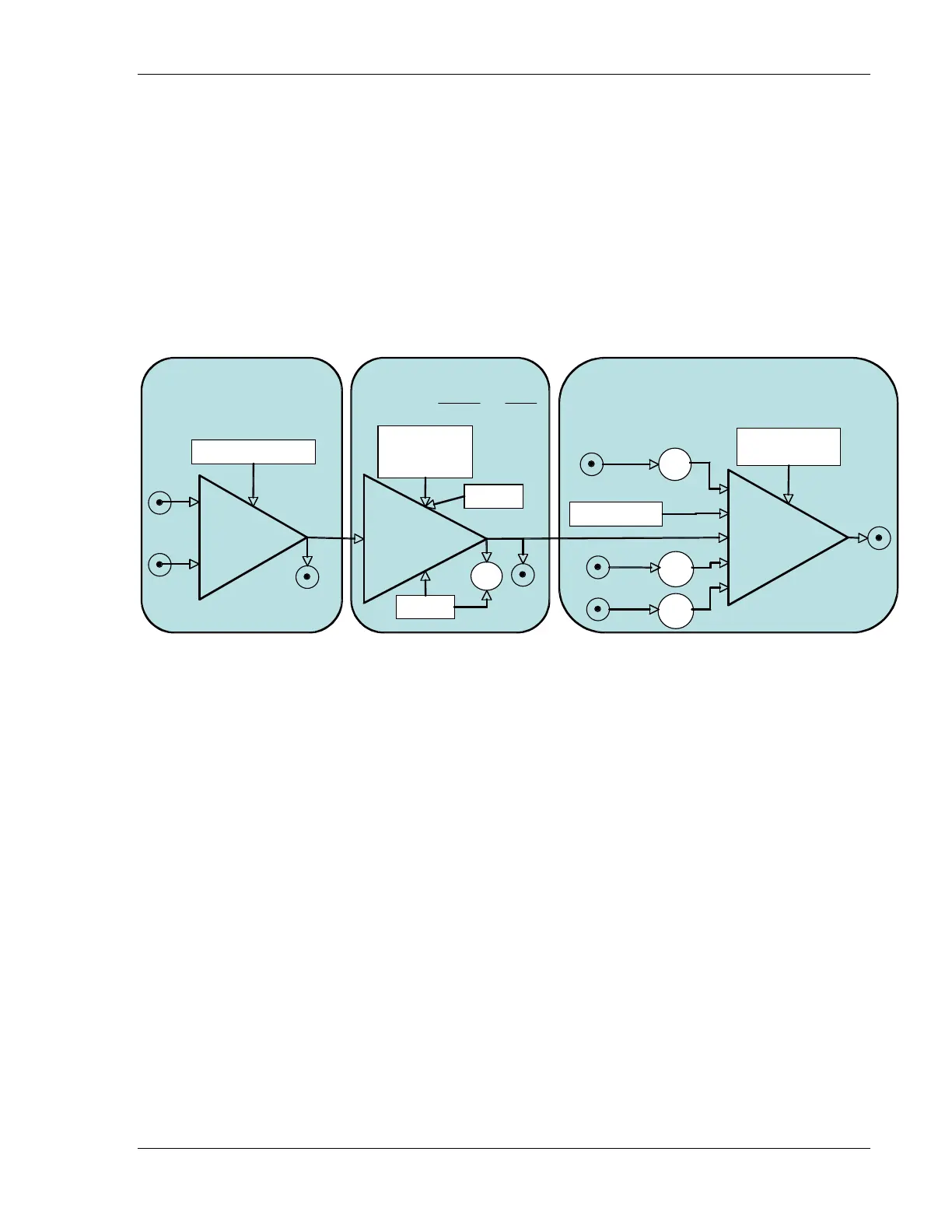
The LB1005 is comprised of three stages of analog signal processing. Figure 7
shows the different sections and how the various input signals are used to derive
the output signal. Each section is briefly described below. See Appendix A for
more detailed specifications.
Proportional-
Integral (PI) Filter
Acquire
Gain (K)
P-I Corner (f
PI
)
LF Gain Limit
Int Hold
LED
Aux
Output
V
Control
= V
Error
K2
π
f
PI
s
1+
s
2
π
f
PI
⎝
⎜
2. Filter Section
Contro
Difference
Amplifier
A
Error
Monitor
-B
Offset Adjust (±10V)
1. Input Section
Error
=
A
−
−B
+
Offset
A
Offset
−
rro
Summing
Amplifier
Output
Sweep Center
+ Voltage Limit
- Voltage Limit
Cente
od 2
Output
Output
Control
Center
+
Span
Sweep
+
Mod1
Mod1
Mod 2
Mod 2
3. Output Section
Sweep
Sweep In
Sweep Span
Span
od1
Mod 1
od1
od 2
Mod 2
+
+
+
+
+
Figure 7: Schematic of LB1005 Signal Architecture
1. Input Section: The input section is a difference amplifier with an adjustable
voltage offset. Common-mode voltages ranging from ±10V can be
subtracted. Error signals (observed at the Error Monitor) that exceed the
voltage range ±330 mV saturate the filter amplifier.
2. Filter Section: This section converts the error signal to a control signal with a
proportional-integral (P-I) filter. Front panel controls adjust the overall loop
gain, the P-I corner frequency, and an optional low-frequency gain limit. A
toggle switch is used to disable/enable the output of the P-I filter for
acquiring lock. See the next section for more details about the transfer
functions available from this filter. An optional TTL input can be used to
disable the error signal input and hold the P-I filter output at its current
value.
3. Output Section: The output section is a summing amplifier that adds the P-I
control signal to other auxiliary signals, such as external sweep and
modulation inputs. The output voltage range of this section can be limited by
rear panel trimpot adjustments.