Getting Started LB1005 Operating Manual
12 Revision 1 Bookham
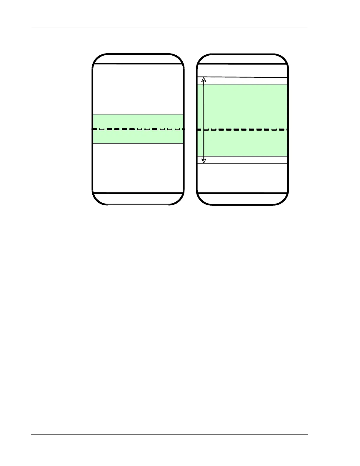
Maximum Output Voltage (+10 V)
Minimum Output Voltage (-10 V)
Positive Voltage Limit V
+
Negative Voltage Limit V
-
Full Voltage Range
∆V
R
= V
+
- V
-
V
+
- 0.1 ∆V
R
V
-
+ 0.1 ∆V
R
Ground (0 V)
Output Signal
Ground (0 V)
Maximum Input Voltage (+10 V)
Minimum Input Voltage (-10 V)
Positive Saturation Voltage (0.33 V)
Negative Saturation Voltage (-0.33 V)
Error Monitor
Figure 6: Voltage limits for the LED Lock Indicator. This LED indicator monitors
when the Error signal exceeds the input saturation voltage range or when the
Output signal is nearing an output rail. The LED lights green (“Locked”) when the
Acquire switch is in either the Lock On or LFGL position, and both the Error and
Output signal voltages fall within the shaded areas above. For all the other
conditions (“Unlocked”), the LED lights red. These conditions are good indicators
when the feedback control is (or is close to) misbehaving.