LB1005 Operating Manual Getting Started
Bookham Revision 1 11
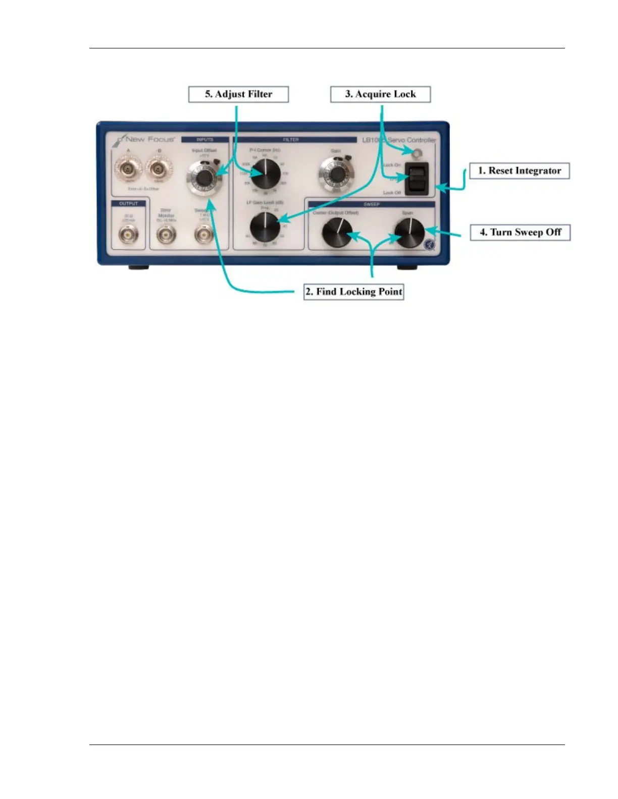
Figure 5: Typical Operation of Controls
The Lock On position disables the low-frequency gain limit and applies the
full integrator gain to the output. Most servo systems should be locked in
this position to minimize DC errors. When correctly locked, the Error Monitor
signal should be very near zero volts, and the LED indicator light should be
green (see Figure 6 for more details.)
4. Turn off sweep: If the output was swept to find the lock point, then it is
good practice to turn the Sweep Span knob to Off after acquiring lock. This
completely disables the sweep signal, and prevents the feedback from
working “overtime” to correct the error induced by the sweep signal.
5. Adjust filter: The P-I Corner frequency can be tuned for optimal
performance and stability. Once optimized, it rarely needs to be revisited.
However, re-tuning the Gain knob is done fairly often to find the maximum
gain setting. A common procedure is to increase the gain until an oscillation
is observed on the Error Monitor, and then reduce the gain until the oscillation
just barely stops.