Detailed Operation LB1005 Operating Manual
14 Revision 1 Bookham
Filter Transfer Functions
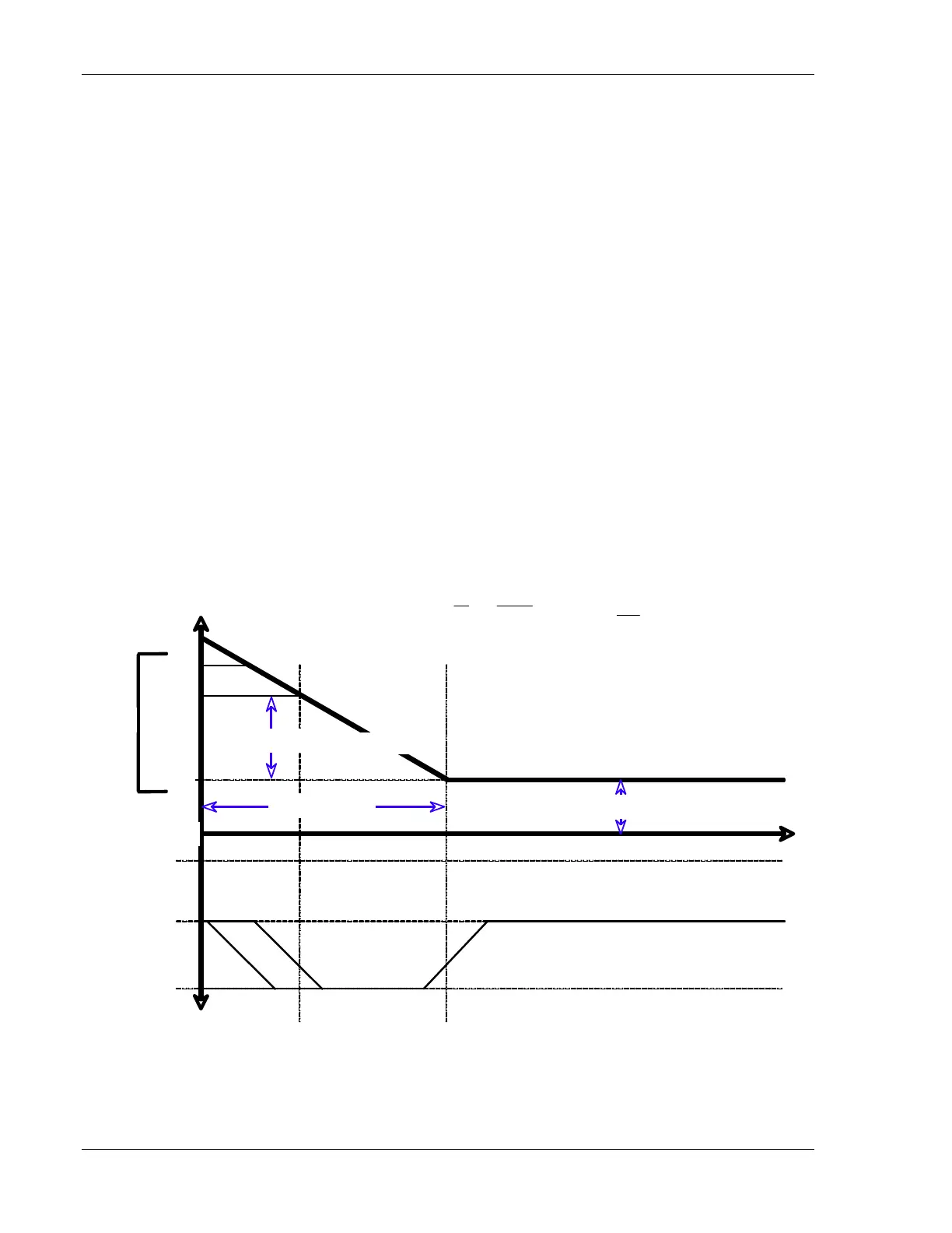
This section describes the transfer functions available from the P-I filter, which
are shown in Figure 8. The filter is specifically designed to have independent
control over the three main parameters that shape the filter frequency response:
• P-I Corner (f
PI
): This is the 3-dB break frequency beyond which proportional
gain dominates over integral gain. For the switch setting Int, the filter
becomes a true integrator with no proportional gain term. In this case, the
integral gain matches that of the 3 kHz P-I Corner setting.
• Gain (K): This is the amount of proportional gain. The gain can be adjusted
continuously on a log scale. Changing this gain does not alter any of the
corner frequencies of the filter.
• LF Gain Limit (g): This is the gain limit for low frequencies, as measured
from the proportional gain value. The integrator is turned off for frequencies
lower than the following 3-dB corner frequency:
f
LFGL
= f
×10
− g(dB )/20dB
[]
. For
the switch setting Prop, the integral gain is completely turned off (g = 0), and
the filter operates only in proportional mode.
f
G(f)
-20 dB/decade
φ
(f)
0°
-90°
90°
Integral gain Proportional gain
“90dB”
“80dB”
Ð
“Prop.”
LF Gain Limit ( g)
P-I Corner (f
PI
)
Gain (K)
FGL
Lock On
LFGL
0 dB
V
Control
s
()
= V
Error
s
()
K
d
1+
s
2
π
f
PI
⎛
⎝
⎜
⎞
⎠
⎟
, d =
s/2
f
PI
LockOn
1+
gs
2
π
f
PI
()
/g LFGL
⎨
⎩
Figure 8: Proportional-integral Filter Gain with Low Frequency Gain Limit