28 System Components
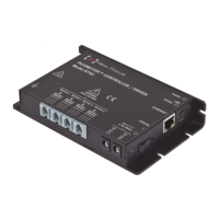
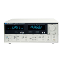
Figure 11: Dimensioned exterior drawings of FSM-CD300B controller/driver.
5.3 FSM Electronics
The FSM electronics are housed in two locations:
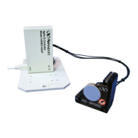
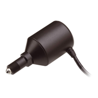
1. The FSM Mirror Head containing the voice coil actuators, the angle
position sensors and the position sensor electronics.
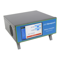
2. The FSM-CD300B Controller/Driver containing the control circuits
(PIDs, calibration factors), current drivers, power supply, user interface and
interlocks.
The mirror head is connected to the controller/driver by a 3-meter long,
15-pin cable. The controller has a universal power supply that can be plugged
 Loading...
