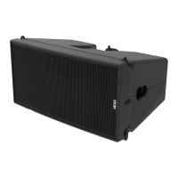
GEO M12 HARDWARE SETUP PROCEDURE Page 47/90
IMPORTANT
Maximum GEO M12 quantity for flown vertical cluster with GMT-LBUMPM12 is 12 (and
eventually less).
Please check NS-1 for mechanical Safety Working Load and acoustic computations.
IMPORTANT
Motor hoist must be rated to support entire cluster weight. Please check configuration
in NS-1 for proper motor hoist rating
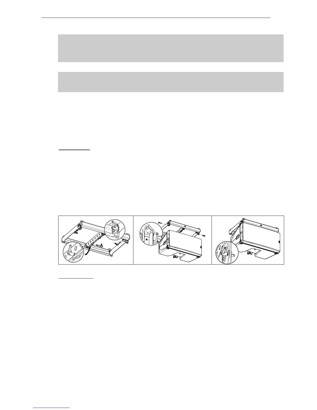
Procedure
GMT-LBUMPM12 can be flipped front and back depending if its connects to GEO M12 Right or Left.
- When connecting GEO M12 Left, bumper front is on the “A” hole index side
- When connection GEO M12 Right, bumper front is on the “G” hole index side
GEO M12 Left
- Position first GEO M12 so that Autorig
TM
is at the bottom
- Position bumper (“A” hole at front) on top of first GEO M12
- Remove the two BL820 quick release pins from their side storage position, and the BL825 quick
release pin of rear bumper link bar.
- Connect bumper front points to GEO M12 with the BL820 quick release pins
- Connect the bumper link bar (0° position) to GEO M12 rear rigging plate (hole marked “bumper”) Lock
with the quick release pin BL0825.
GEO M12 Right
- Position GEO M12 so that Autorig
TM
is at the top and set in automatic lock position
- Position bumper (“G” hole at front) on top of first GEO M12
- Remove the the BL825 quick release pin of rear bumper link bar.
- Connect bumper front points to GEO M12, front points will lock automatically
- Connect the bumper link bar (0° position) to GEO M12 rear rigging plate (hole marked “bumper”) Lock
with the quick release pin BL0825.
 Loading...