- If required, connect GMT-EXBARM12L to GMT-LBUMPM12 by inserting GMT-EXBARM12L clevis
pins into GMT-LBUMPM12 “B” and “F” holes
- Insert shackle(s) in bumper or in extension in required hole(s) as indicated in NS1 design and secure
shackle bolt(s);
o “A” to “G” on GMT-LBUMPM12
o Or “H” to “Q” if using GMT-EXBARM12L
o If using 2 hoists, connect these using extreme points
(“A” and “G”, or “H” and “Q”)
- Connect hoist hook(s) to shackle(s) and lift assembly to sufficient height in order to connect a second
GEO M12
IMPORTANT
Ensure hoist hook(s) is (are) properly secured to GMT-LBUMPM12 or GMT-EXBARM12L
Ensure that all quick release pins are locked
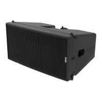
Subsequent GEO M12s
- Position second GEO M12 cabinet with AutoRig
TM
in automatic lock position, and lock front points to
first GEO M12
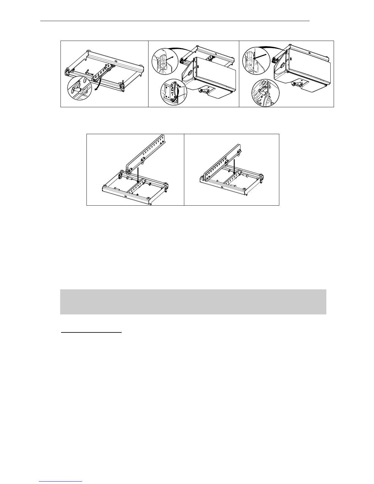
- Unlock GEO M12 link bar
- Pull the latch to engage the guide in GEO M12 rear slot.
- Adjust the angle by inserting quick release pin BL820 in proper hole.
- Connect subsequent GEO M12 cabinets as with second.
 Loading...