Page 58/90 GEO M12 HARDWARE SETUP PROCEDURE
Required items
- 1 or 2 hoists (not provided).
- 2 x VNT-BUMPM12
- 1 x VNT-EXBARM12 for extended positive and negative bumper angles
IMPORTANT
When flying MSUB18 & GEO M12 cluster, VNT-BUMPM12 must be set at 0°
- If cluster is flown from 2 points, bumper must be maintained horizontal in its definitive
position as well as when lifting or lowering the cluster
- If cluster is flown from a single point, extension bar must be used and hoist connected
to “G” position
IMPORTANT
Maximum quantity for flown vertical cluster with VNT-BUMPM12 is:
N
GEOM12
+ 1.5*N
MSUB18
<= 12
Please check NS-1 for mechanical Safety Working Load and acoustic computations.
IMPORTANT
Motor hoist must be rated to support entire cluster weight. Please check configuration
in NS-1 for proper motor hoist rating
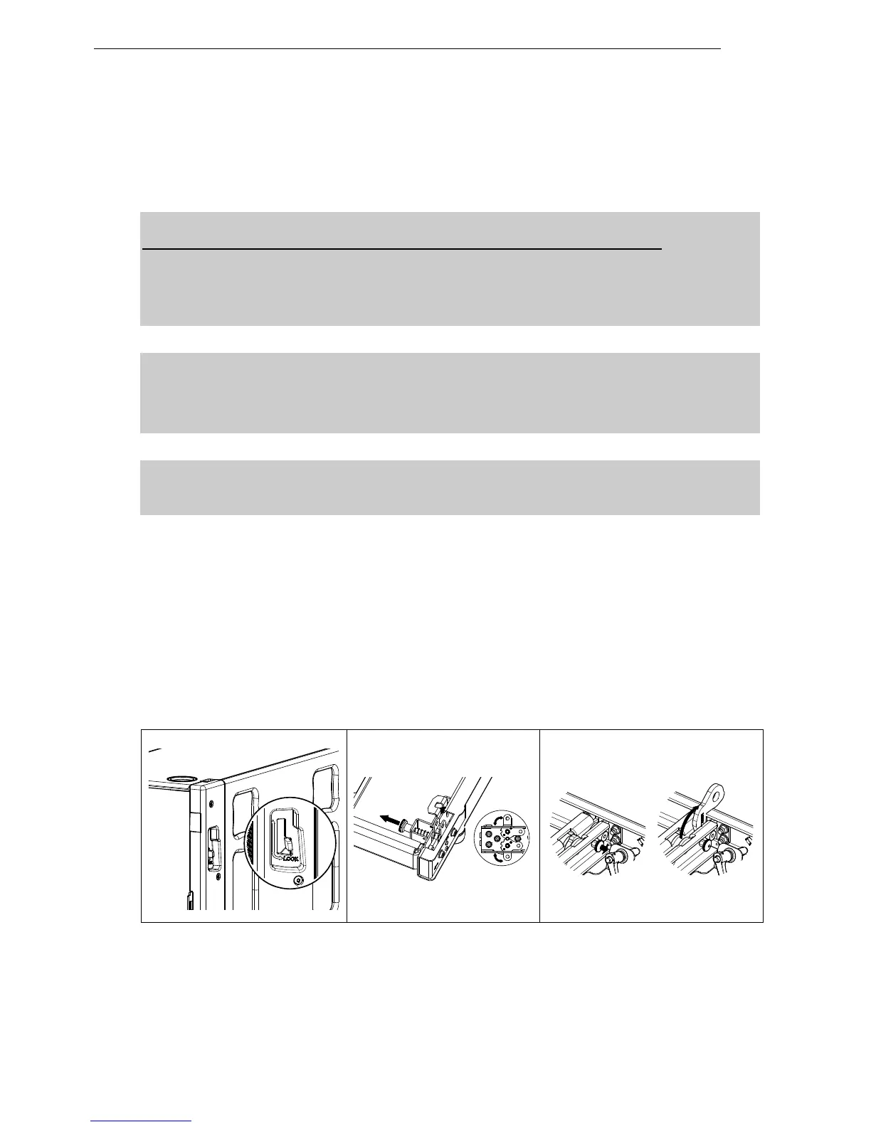
Procedure
- Position first MSUB18 and unlock front and rear rigging points
- Pull the bumper front latches, rotate the lower links so that connection points are double leg and
release the latches.
- Position bumper on top of first MSUB18 and lock front and rear points to the bumper with 2 BL820
quick release pins.
- If flying with bumper only, pull front and rear center latches, and release front and rear bumper
connecting points.
 Loading...