Page 64/90 GEO M12 HARDWARE SETUP PROCEDURE
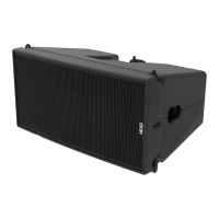
Subsequent MSUB18-I
- Remove the 4 corner plates (Tx30)
- Insert the axis across front and rear rigging points, insert safety clips and secure these by bending
their legs
- Connect subsequent MSUB18-I as with second.
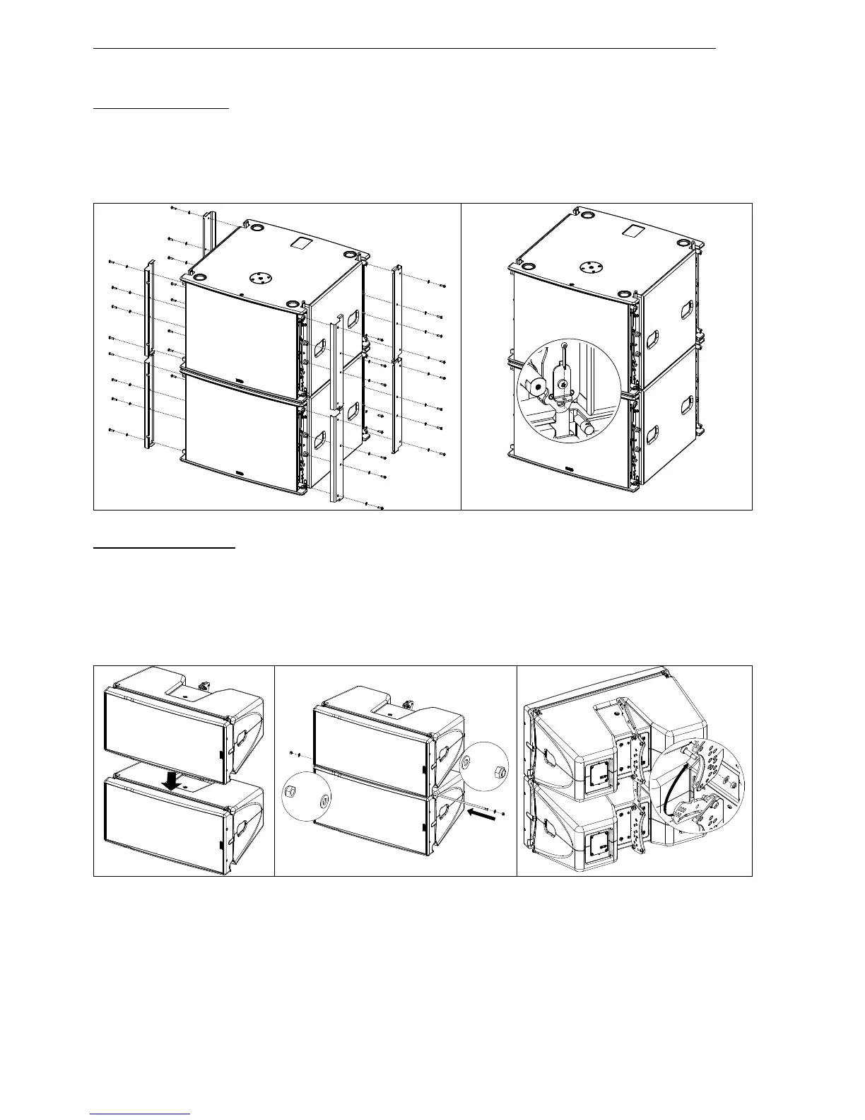
Subsequent GEO M12-I
- Position second GEOM12-I.
- Connect both cabinets by inserting the axis through front holes and secure axis with brake nuts.
- Adjust the appropriate inter-angle value with the linkbar and secure with the provided screws (1 x
shoulder screw (D10x20), 2 x washers (M10), 1 x brake nut (M8).
- Connect subsequent GEO M12-I cabinets as with second.
 Loading...