RAY SUBS IMPLEMENTATION Page 39/54
Table below lists these values for typical angle values:
TILT ANGLE 0° 5° 10° 15° 20° 25° 30° 35° 40° 45°
DELAY τ (ms)
0.0 0.1 0.3 0.4 0.5 0.6 0.8 0.9 1.0 1.1
1 RS18
DISTANCE (cm)
0 5 9 13 18 22 26 30 33 37
DELAY τ (ms)
0.0 0.3 0.5 0.8 1.0 1.3 1.5 1.7 1.9 2.1
GROUP
2 RS18s
DISTANCE (cm)
0 9 18 27 36 44 52 60 67 74
DELAY τ (ms)
0.0 0.4 0.8 1.2 1.6 1.9 2.3 2.6 2.9 3.2
GROUP
3 RS18s
DISTANCE (cm)
0 14 27 40 53 66 78 89 100 110
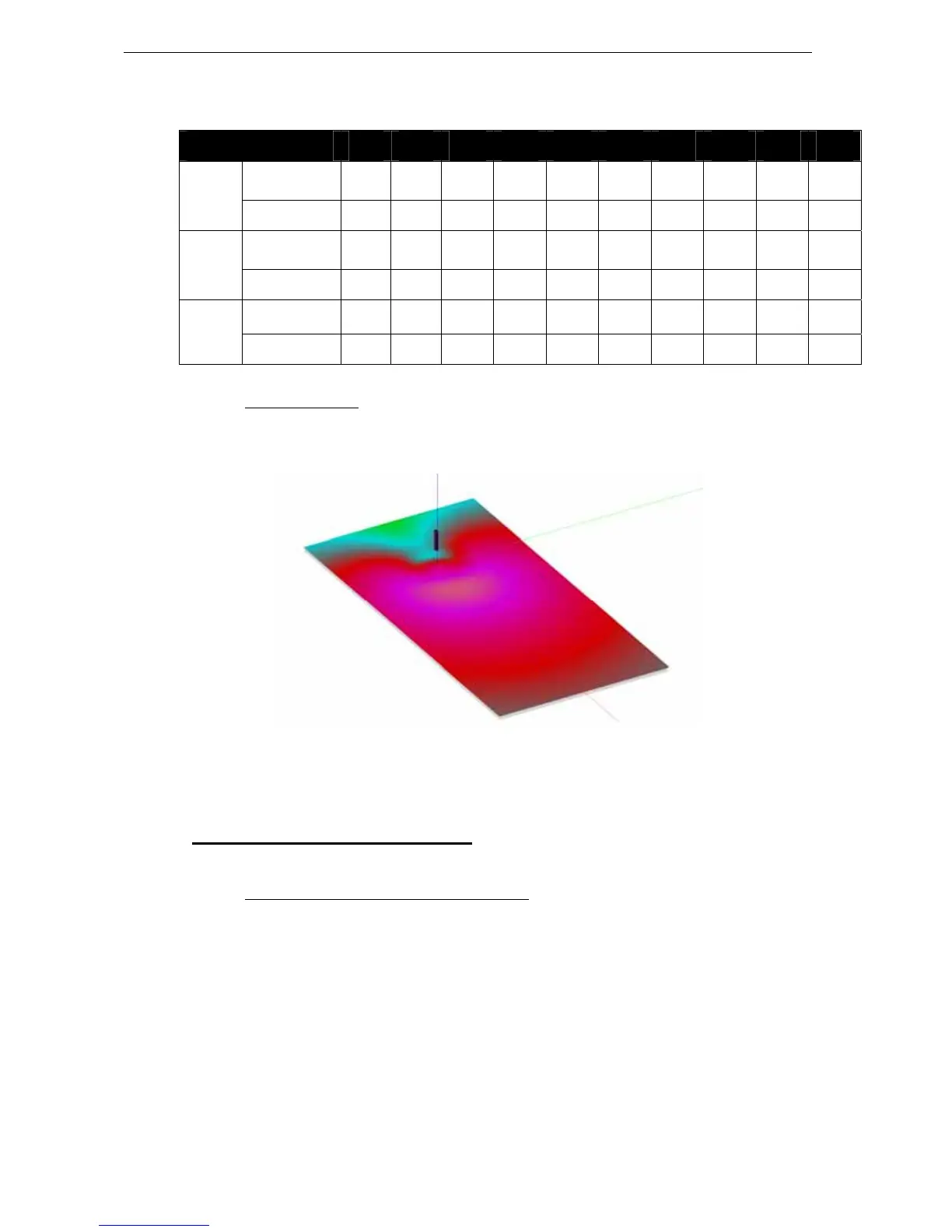
7.3.3 Coverage result
Below figure shows coverage control over distance with a “steering” delay sequence corresponding to a
15° tilt down.
10 RS18 CLUSTER OVER 75M/200FT, STEERED 15° DOWN
7.4 Aligning RS18s with main system
7.4.1 NEXO systems acoustic reference point
The NX TDControllers factory presets are optimised to provide the best possible crossover between the
RS18s and the Main NEXO system. These crossover algorithms are defined for speaker acoustic
reference points being aligned.
The acoustic reference point on all NEXO products is the front of each cabinet, therefore:
• RS18’s reference point in Omni Mode is center of the front grid
• RS18’s reference point in Directional Mode is center of the face opposite to connector panel.
 Loading...