INSTALLATION
System Diagram
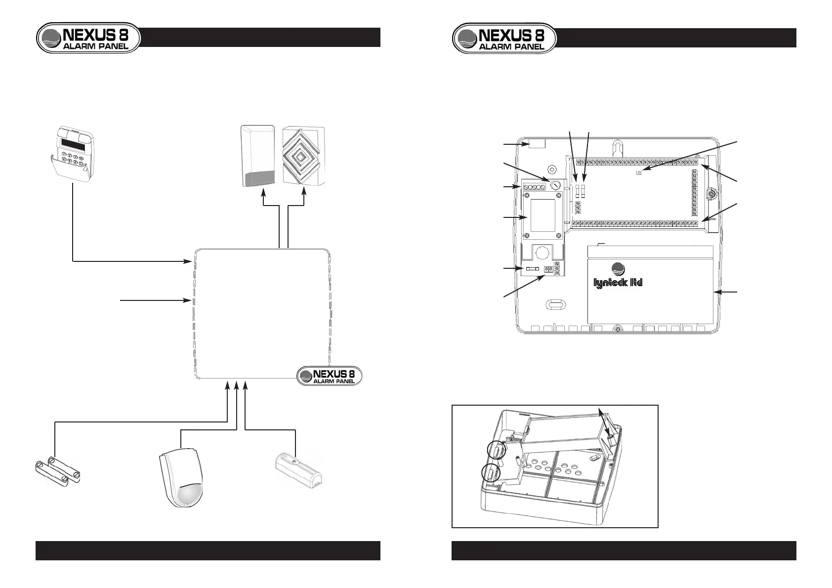
CONTROL PANEL INTERNAL LAYOUT
GEAR TRAY REMOVAL
• To release the gear tray,
unscrew and tilt away from
backplate.
• To replace, first place left
side under catches, then tilt
home and replace screw.
5
PANEL LAYOUT • GEAR TRAY REMOVAL
4
SYSTEM DIAGRAM
Mains cable
entry
Mains fuse
Mains
connection
terminals
Component
connection
terminals
Tamper switch
Auxiliary fuse Bell fuse
Battery
Battery
connection
terminals
Transformer
Battery fuse