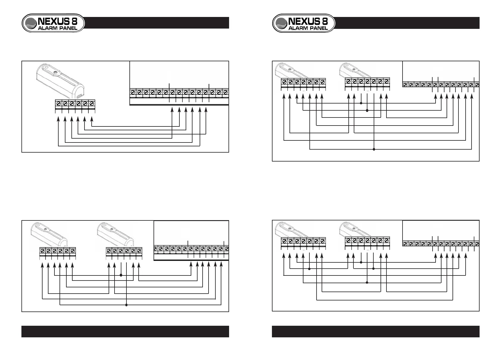
VIBRATION DETECTORS
• If two or more detectors are connected to one zone, power is wired in
parallel, whereas alarm and tamper circuits must be wired in series.
• Where 6-cores are used to wire latching detectors, power supply is taken
from tamper circuit. The zones’ + terminal should not be used.
12
NEXUS 8
PCB
- A A T T +
ZONE 3
ZONE 2
T T - + A A
6-Core Cable
NEXUS 8
PCB
- A A T T +
ZONE 3
ZONE 2
T T - + A A
T T - + A A
Lynteck
Vybe
Connection
terminals
VIBRATION DETECTOR WIRING
13
VIBRATION DETECTOR WIRING
NEXUS 8
PCB
Single Non-latching Vibration Detector
Two or more Non-Latching Vibration Detectors
Latching Vibration Detector (7 - Cores)
T T C - + A A
T T C - + A A
C
BELL/STROBE
LATCH
ZONE 1
Lynteck
Pro-Vybe
Lynteck
Pro-Vybe
NEXUS 8
PCB
Latching Vibration Detector (6 - Cores)
T T C - + A A
T T C - + A A
C
BELL/STROBE
LATCH
ZONE 1
Lynteck
Pro-Vybe
Lynteck
Pro-Vybe
- A A T T +
- A A T T +
NOT USED
6-Core Cable
8-Core Cable (7-cores Used)
6-Core Cable
© Lynteck Ltd. 1998 LY68-030-68
ZONE 3
ZONE 2