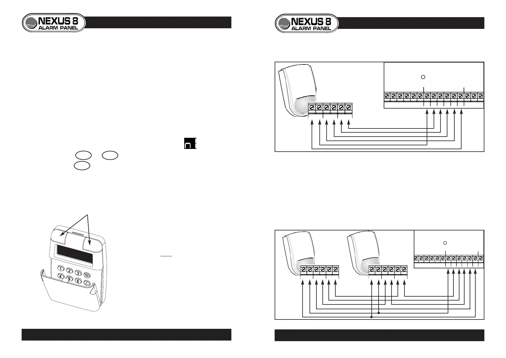
PIR DETECTORS
• Consult detectors’ instructions before installation.
• If two or more PIRs are connected to a zone, wire power in parallel,
alarm and tamper in series.
• Use 6-core cable.
11
LED
NEXUS 8
PCB
- A A T T +
ZONE 2
ZONE 1
+12v- TAMP RELAY
6-Core Cable
Harrier
PIR
LED
NEXUS 8
PCB
- A A T T +
ZONE 2
ZONE 1
+12v- TAMP RELAY
+12v- TAMP RELAY
P.I.R. WIRING
Single PIR
Two or more PIRs
ADDRESSING ADDITIONAL KEYPADS
If two or more keypads are used in an installation, each has to be assigned
an address number in order to communicate with the end-station. This
address number is factory set to 1 and so must be changed on additional
keypads.
To set address number on an additional keypad
• Ensure keypad to be added is not yet powered.
• Remove keypad’s front cover.
• Electrically connect keypad to endstation.
• The keypad will display its address number i.e.
• Press 1 to 4 to change keypads address.
• Press YES to accept and a conformation bleep will be heard.
• Replace keypad cover and test keypad can control the system.
PANIC ATTACK
• The remote keypad also features a
panic attack function.
• Panic attack is operated by
pressing both buttons situated
above the keypad display.
• Panic attack function can be
disabled if required. (See
programming menu p.20)
10
PROGRAMMING ADDITIONAL KEYPADS