SCC Quick Start Guide 10 ni.com
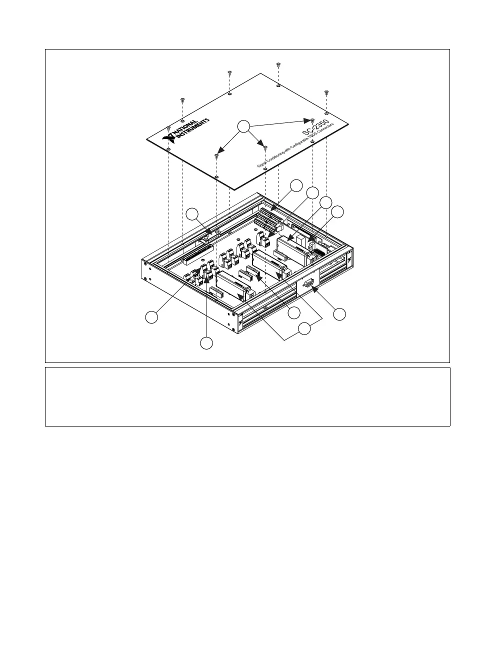
Figure 8 shows the SC-2350 carrier with the SCC modules installed.
Figure 8. SC-2350 Carrier Installation Diagram
Connecting Digital Signals (Optional)
The SC-2345/2350 has a 42-position, triple-row screw-terminal block for
connecting to DAQ device digital signals. Depending on the DAQ device
you are using, you can connect the terminal block to various digital signals.
Refer to Figure 10 for signals of E Series, B Series, or M Series
Connector 0. The SC-2345 Quick Reference Label identifies the location
of each signal on the terminal rows A to C. The terminal label numbers
correspond to the pin number location of each signal on the 68-pin DAQ
device connector. Refer to the DAQ device documentation for more
information about this connector.
1 Cover Screws
2 Screw Terminal Block
3 TEDS Screw Terminal
4 SCC Modules—Analog Output
5SCC-PWR
XX
6 D-SUB Panelette
7 SCC Modules—Analog Input
8 Connector Block Sockets
9 TEDS Screw Terminal: RETURN Screw Terminal
10 TEDS Screw Terminal: DATA+ Screw Terminal
11 Strain-Relief Panelette
2
3
4
5
6
7
8
9
10
11
1
 Loading...