© National Instruments Corporation 19 SCC Quick Start Guide
lowpass filter SCC module. Figure 16 shows how to install analog input
modules on the SC-2345 carrier.
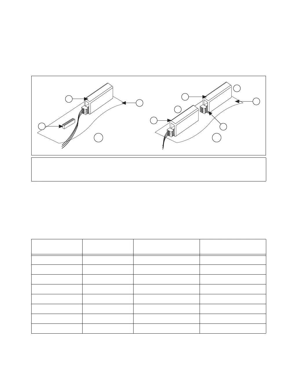
Sometimes, you can cascade two analog input SCC modules together on a
single analog input channel to form a dual-stage configuration. The first
stage of a dual-stage analog input configuration can be in sockets J9 to J16.
The second stage of a dual-stage analog input configuration can be in
sockets J1 to J8.
Figure 16. Single- and Dual-Stage Analog Input SCC Configuration
for SC-2345 Connector Block Socket
Table 3 shows all the analog input SCC modules that you can configure
on the SC-2345 carrier and whether the modules support single-stage,
dual-stage, or both configurations.
A Single-Stage Analog Input
B Dual-Stage Analog Input
1 J9 Connector Block
(SCC Module Not Installed)
2 Analog SCC Plugged into J1
3 SC-2345 Carrier
4 Analog SCC Plugged into J9
5 First Stage
6 Second Stage
7 Do Not Connect Any Signals to
the Second-Stage SCC
Table 3. SCC Modules and Dual-Stage Compatibility
SCC Modules
Single-Stage Analog
Input (J1–J8)
First Stage of Dual-Stage
Analog Input (J9–J16)
Second Stage of Dual-Stage
Analog Input (J1–J8)
SCC-AIXX Yes Yes No
SCC-A10 Yes Yes No
SCC-RTD01 Ye s Yes No
SCC-CI20 Yes Yes No
SCC-ACC01 Yes Yes No
SCC-TC0X Yes Ye s No
SCC-FV01 Ye s No Yes
SCC-LPXX Yes Ye s Yes
SCC-XXXX
3
2
1
SCC-XXXX
3
2
1
SCC-XXXX
3
2
1
5
A
6
B
4
2
2
1
3
3
7
 Loading...