SCC Quick Start Guide 26 ni.com
SCC-LP01 Analog Input»Voltage Max/Min = ±10 V
SCC-LP02 Analog Input»Voltage Max/Min = ±10 V
SCC-LP03 Analog Input»Voltage Max/Min = ±10 V
SCC-LP04 Analog Input»Voltage Max/Min = ±10 V
SCC-RLY01 Digital Output Use default
SCC-RTD01 Analog Input»Temperature»RTD Current Excitation Value = 1 mA
Excitation Source = Internal
RTD Type = #
R
0
= #
Resistance Configuration = #
SCC-SG01 Analog Input»Strain Gage Strain Configuration = Quarter Bridge I
Gage Resistance = 120 Ω
Gage Factor = #
SCC-SG02 Analog Input»Strain Gage Strain Configuration = Quarter Bridge I
Gage Resistance = 350 Ω
Gage Factor = #
SCC-SG03 Analog Input»Strain Gage Strain Configuration = Half Bridge I
Gage Resistance = #
Gage Factor = #
Poisson Ratio = #
SCC-SG04 Analog Input»Strain Gage Strain Configuration = Full Bridge I
Gage Resistance = #
Gage Factor = #
Analog Input»Custom Voltage with
Excitation
Max/Min = ±100 mV
Bridge Type = Full Bridge
Excitation Source = Internal
Excitation Value = 2.5 V
SCC-SG24 Analog Input»Strain Gage Strain Configuration = Full Bridge I
Excitation Value = 10 V
Gage Resistance = #
Gage Factor = #
Analog Input»Custom Voltage with
Excitation
Max/Min = ±100 mV
Bridge Type = Full Bridge
Excitation Source = Internal
Excitation Value = 10 V
SCC-SG11 Digital Output Use default
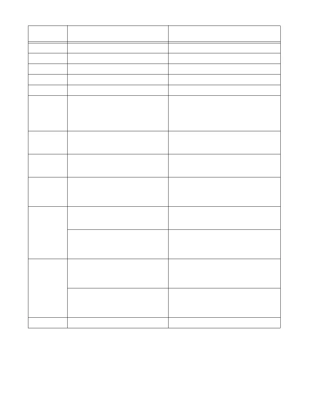
Table 4. SCC Module and Corresponding NI-DAQmx Measurement Type (Continued)
SCC Module
Recommended NI-DAQmx
Measurement Type
Recommended
Parameter Settings
1
 Loading...