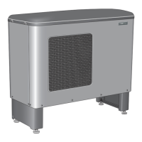
The NIBE F2015 is an air/water heat pump designed for the Nordic climate, primarily intended for heating small houses, apartment blocks, and small industrial premises. It uses outdoor air as its heat source. The F2015 is a Swedish-made quality product known for its long lifespan and reliable operation.
Function Description
The F2015 utilizes outdoor air to provide heating and hot water. It is equipped with an automatic 2-stage capacity control fan, which operates only when necessary (F2015-6 kW has one fan speed). The heat pump can be used with various heating systems, including radiators, underfloor heating, and fan convectors, and can be combined with electric boilers, oil-fired boilers, or equivalent systems. The heat pump includes an advanced control system for optimal control, starting from a smart signal from another controller or thermostat. It can also be controlled by a specially designed controller, SMO 10, which connects and disconnects additional heat and controls switching between room heating and hot water heating. Accessories like an extra shunt group and pool control can be connected if SMO 10 is present.
The F2015 can deliver high-temperature hot water efficiently at low outdoor temperatures. If the outdoor temperature drops below a certain level, the stop temperature for all heating must occur with additional heat. The F2015 is manufactured in three sizes: 6, 8, and 11 kW, and is designed for a long service life.
Important Technical Specifications
The F2015 is available in 6, 8, and 11 kW models.
- Operating Voltage: 230 V 1AC 50Hz.
- Nominal flow heating medium: 0.16 l/s (F2015-6), 0.20 l/s (F2015-8), 0.25 l/s (F2015-11).
- Min/max pressure heating medium side: 0.5/5.5 bar.
- Airflow: 1500 m³/h (F2015-6), 1700/2000 m³/h (F2015-8), 1700/2000 m³/h (F2015-11).
- Nominal output, fan: 70 W (F2015-6), 90/130 W (F2015-8), 90/130 W (F2015-11).
- Fuse: 20 A (F2015-6), 20 A (F2015-8), 25 A (F2015-11).
- Enclosure class: IP 24.
- Refrigerant volume (R407C): 1.9 kg (F2015-6), 2.1 kg (F2015-8), 2.1 kg (F2015-11).
- Connection heating medium male Ø: G1 (28 mm).
- Height with stand: 1045 mm.
- Width: 1200 mm.
- Depth: 440 mm.
- Weight: 120 kg (F2015-6), 126 kg (F2015-8), 132 kg (F2015-11).
- Colour: Dark grey.
- Lowest operational point, outdoor air/flow line: -15/45 °C.
- Highest operational point, outdoor air/flow line: 35/58 °C.
Sound pressure levels:
- At 1 m, fan low/high: 51/57 dB(A) (F2015-6), 51/56 dB(A) (F2015-8), 51/56 dB(A) (F2015-11).
- At 4 m, fan low/high: 39/44 dB(A) (F2015-6), 39/44 dB(A) (F2015-8), 39/44 dB(A) (F2015-11).
- At 10 m, fan low/high: 31/36 dB(A) (F2015-6), 31/36 dB(A) (F2015-8), 31/36 dB(A) (F2015-11).
Usage Features
The F2015 can be docked with various systems:
- F2015 docked with VVM 300 (fixed condensing): Controlled by VVM 300, which manages the heating system and prioritizes hot water charging.
- F2015 docked to the oil-fired/pellet boiler together with SMO 10 and water heater (floating condensing): SMO 10 controls the F2015, oil-fired boiler, circulation pumps, and shunts. F2015 works with floating condensing, prioritizing hot water charging via a three-way valve. Additional heat from the oil-fired boiler is engaged if F2015 cannot meet the heating demand.
- Several F2015 together with SMO 10 and water heater (floating condensing): SMO 10 controls up to nine F2015 units, immersion heaters, circulation pumps, shunts, etc. F2015 works with floating condensing, prioritizing hot water charging via a three-way valve. Additional heat is engaged from the oil-fired boiler or immersion heater if F2015 cannot meet the heating demand.
- F2015 docked to an electric/oil boiler (floating condensing): Controlled by a room thermostat. F2015 works with floating condensing on the return from the heating system. Additional heat is shunted in using existing control equipment if F2015 cannot meet the heating requirement.
- F2015 docked with wood fired boiler and hot water heater (fixed condensing): F2015 charges the water heater/accumulator tank. When the firewood boiler is active, the heat pump and immersion heater are disconnected. Self-circulation through the heat pump is prevented by a check valve.
Control System:
The F2015 is equipped with an internal electronic controller that handles all functions necessary for heat pump operations. It manages defrosting, stop at max/min temperature, compressor heater operation, and pressure switch safe control. The number of starts and operating time can be read. The integrated controller is set during installation and used during service. Under normal operation, the homeowner does not need to access the controller. An integrated electronic return line sensor limits the return temperature. F2015 can be switched on/off via signals from other control equipment or a thermostat. If F2015 is controlled by the accessory SMO 10, the control is described in the instructions supplied with SMO 10. SMO 10 communicates with F2015, and measurements from F2015 can be adjusted and read off in SMO 10.
Adjustments:
The charge flow can be adjusted by measuring the temperature difference (ΔT) between the flow temperature and the return temperature during hot water charging or at high load. This is done by using measurements in Channel T2 (flow temperature) less Channel T3 (return temperature). The temperature difference (ΔT) is adjusted using a circulation pump and mixing valve. Adjustment is performed with stable operation about 5 minutes after start, or about 5 minutes after defrosting with a cold outdoor temperature.
Maintenance Features
General Maintenance:
The F2015 is equipped with control and monitoring equipment, but some exterior maintenance is still necessary.
- Regular checks: Check throughout the year that the intake grilles are not clogged by leaves or snow.
- Condensation water: During cold months, ensure there isn't a build-up of ice or frost under the unit. The condensation water trough KVT 10 accessory is available for management and removal of condensation. Strong wind combined with heavy snowfall can block the intake and exhaust air grilles. Ensure there is no snow on the grilles.
- Cleaning: The outer casing can be cleaned using a damp cloth. Avoid spraying water into the grilles or the sides, as that water can penetrate into F2015. Do not use alkaline cleaning agents.
WARNING: The fan rotates, so exercise caution during maintenance.
Electrical Connections:
Electrical installation and service must be carried out under the supervision of a qualified electrician. All electrical installations must be carried out in accordance with applicable regulations. The live external control must be taken into consideration when connecting.
- Incoming feed cable: Supplied and factory connected to terminal block -X1. Approximately 1.8 m cable is accessible outside the heat pump.
- Routing of cables: Cables for heavy current should be routed through the cable glands on the heat pump's left-hand side, and signal cables from the rear.
- Connection: The heat pump must be connected without the permission of the electricity supplier and must be connected under the supervision of a qualified electrician.
- Circuit breaker: A miniature circuit breaker (MCB) should be used, with motor characteristic "D" (compressor operation). F2015 does not include an omnipole circuit breaker on the incoming power supply. The heat pump's supply cable must be connected to a circuit-breaker with at least a 3 mm breaking gap. When the building is equipped with an earth-fault breaker, the heat pump should be equipped with a separate one. Incoming supply must be 230 V 1AC 50Hz, via distribution boards with fuses.
- Insulation test: An insulation test is to be carried out in the building, not on the heat pump.
- Control signal cable: Connect control signal cable for thermostats to terminal (30). Cable type: unscreened LiYY, screened LiYCY. Cable area at least 0.22 mm² with cable length less than 50 m.
- Relevant signal cable: Alternatively, the relevant signal cable is connected from terminal (44) on the control card (34) to SMO 10/VVM 300.
- Charge pump: Connect to terminal block (11) or to separate supply. If F2015 is deenergized and the charge pump is connected to terminal block (11), there is a risk of freezing.
- Common alarm: A common alarm can be connected to terminal (11).
External Heat Cable:
F2015 is equipped with a terminal block for the Condensation water trough KVT 10 accessory. Max load is 200 W.
Outside Sensor:
An outdoor sensor (15) is located on the underside of F2015.