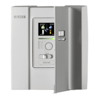
Component positions
L N 1 1 0 2 3 4PE
1 2 3 4
LEK
AA2
AA4-XJ3
X1
SF1
AA5
PF3
AA4
AA3
X2
AA7
AA4-XJ4
L N 1 1 0 2 3 4PE
1 2 3 4
LEK
Electrical components
Base cardAA2
Input circuit boardAA3
Display unitAA4
AA4-XJ3 USB socket
AA4-XJ4 Service outlet (No function)
Accessory cardAA5
Extra relay circuit boardAA7
Miniature circuit breaker, 10 AFA1
Emergency mode relayK2
Terminal block, incoming electrical supplyX1
Terminal block, AUX4 - AUX6X2
SwitchSF1
Serial number platePF3
Cable grommet, incoming supply electricity, power
for accessories
UB1
Cable gland, signalUB2
Designations in component locations according to standard IEC 81346-
1 and EN 81346-2.
NIBE SMO 40Chapter 3 | The Control Module Design10
3 The Control Module Design

 Loading...