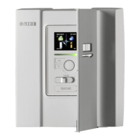
General
• Disconnect SMO 40 before insulation testing the
house wiring.
• If the building is equipped with an earth-fault breaker,
SMO 40 should be equipped with a separate one.
• SMO 40 must be installed via a circuit breaker with a
minimum breaking gap of 3 mm.
• For the electrical wiring diagram for the control mod-
ule, see page .69.
• Use a three core, screened cable for communication
with the heat pump.
• Communication and sensor cables to external connec-
tions must not be laid close to high current cables.
• The minimum area of communication and sensor
cables to external connections must be 0.5 mm² up
to 50 m, for example EKKX, LiYY or equivalent.
• When cable routing into SMO 40, cable grommets
(UB1 and UB2, marked in image) must be used.
NOTE
The switch (SF1) must not be moved to "" or
" " until the boiler water has been filled in the
system. The compressor in the heat pump and
any external additional heat can be damaged.
NOTE
Electrical installation and any servicing must
be carried out under the supervision of a quali-
fied electrician. Disconnect the current using
the circuit breaker before carrying out any ser-
vicing. Electrical installation and wiring must
be carried out in accordance with the applicable
provisions. When installing SMO 40, NIBE’s
air/water heat pump and any additional heat
must be disconnected from the power supply.
Caution
See outline diagram for your system for phys-
ical location of the temperature sensor that is
to be installed.
Caution
The relay outputs on the accessory board (AA5)
may be subjected to a max load of 2 A (230 V)
in total.
L N 1 1 0 2 3 4PE
1 2 3 4
LEK
MINIATURE CIRCUIT-BREAKER
The control module operating circuit and parts of its in-
ternal components are internally fused by a miniature
circuit breaker (FA1).
19Chapter 5 | Electrical connectionsNIBE SMO 40
5 Electrical connections

 Loading...