Lay the PWM cable in the upper
duct, route it behind the metal
housing to the communication
board (AA23) Secure using cable
ties.
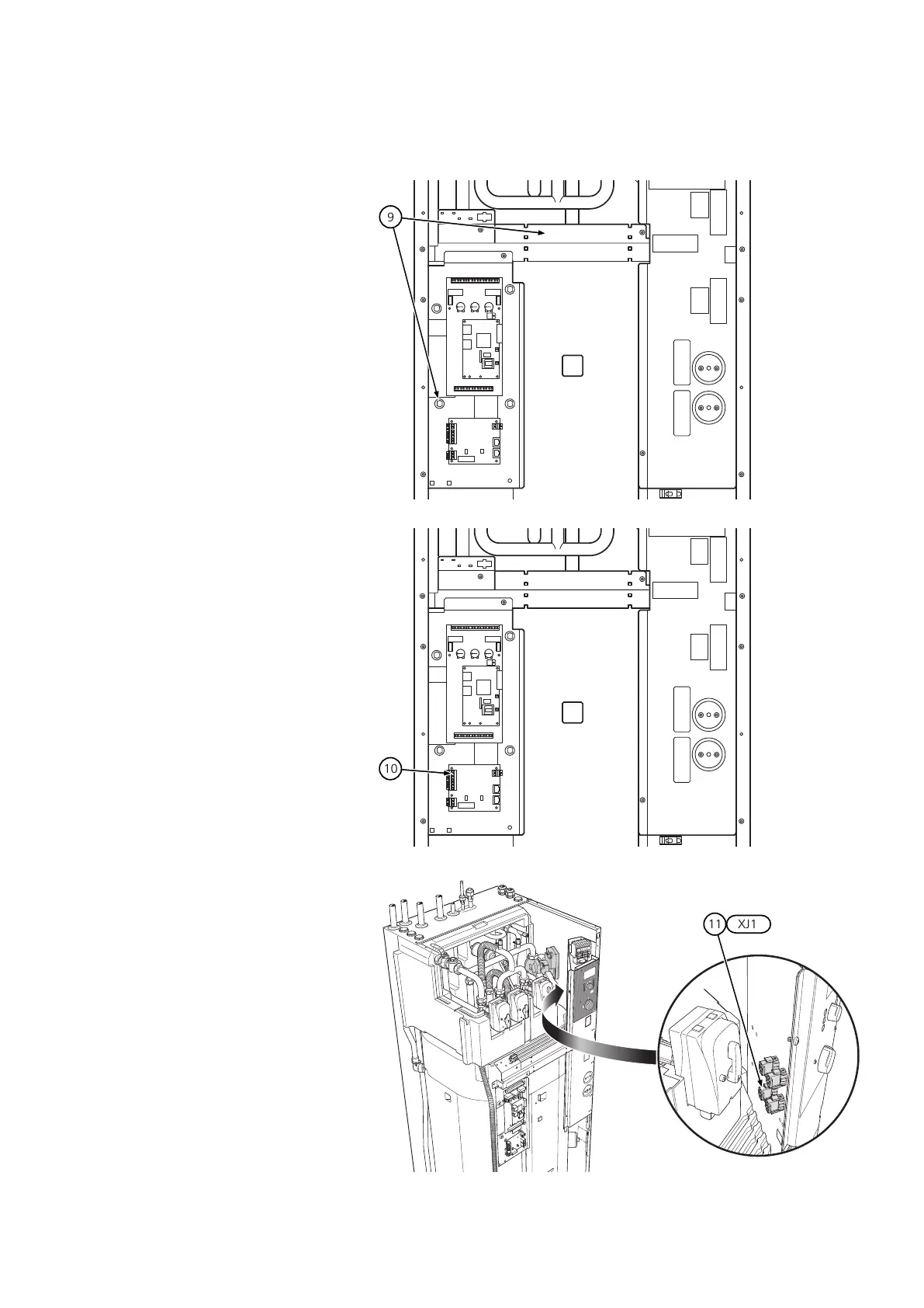
9.
Connect the PWM cable to the
communication board (AA23), ter-
minal X1.
Brown core (PWM) to terminal 1.
Blue cable (PWM GND) to termin-
al 2.
10.
Connect the power cable to termin-
al XJ1.
11.
23| GB