Optional connections
LOAD MONITOR
Integrated load monitor
VVM 225 is equipped with a simple form of integrated
load monitor, which limits the power steps for the
electric additional heat by calculating whether future
power steps can be connected to the relevant phase
without exceeding the specified main fuse. If the current
would exceed the specified main fuse, the power step
is not permitted. The size of the property’s main fuse
is specified in menu 5.1.12.
Load monitor with current sensor
When many power-consuming products are connected
in the property at the same time as the electric additional
heat is in operation, there is a risk of the property’s main
fuses tripping. VVM 225 is equipped with a load monitor
that, with the aid of current sensors, controls the power
steps for the electric additional heat by redistributing
the power between the different phases or disengaging
the electric additional heat in event of an overload in a
phase. Reconnection occurs when other current con-
sumption is reduced.
Caution
Activate phase detection in menu 5.1.12 for
full functionality.
Connecting current sensors
NOTE
If the installed air/water heat pump is frequency
controlled, it will be limited when all power
stages are disconnected.
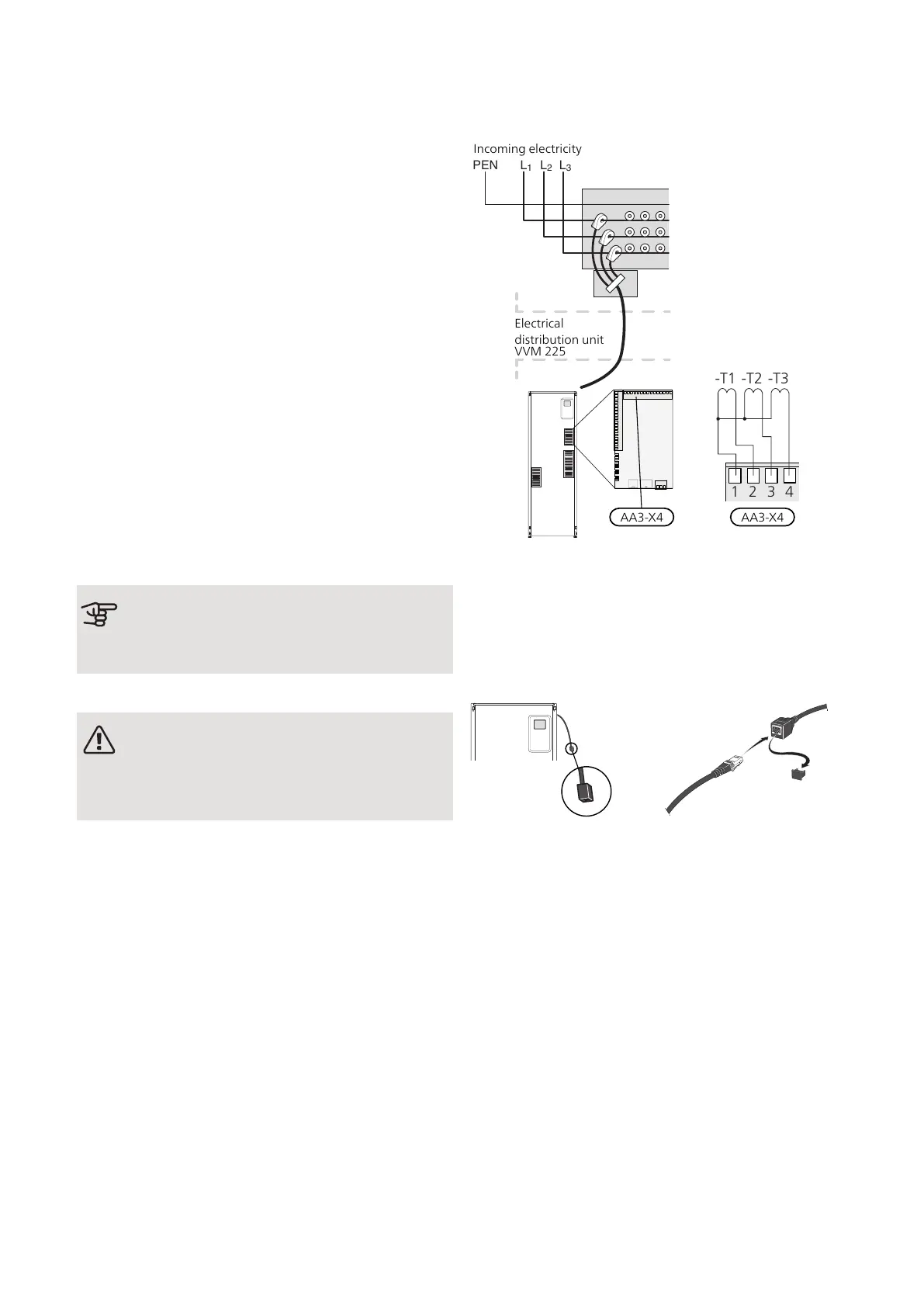
A current sensor should be installed on each incoming
phase conductor in to the distribution box to measure
the current. The distribution box is an appropriate install-
ation point.
Connect the current sensors to a multi-core cable in an
enclosure directly adjacent to the electrical distribution
unit. The multi-core cable between the enclosure and
VVM 225 must have a cable area of at least 0.5 mm².
Connect the cable to the input board (AA3) on terminal
block X4:1-4 where X4:1 is the common terminal block
for the three current sensors.
AA3-X4 AA3-X4
Electrical
distribution unit
VVM225
Incoming electricity
If the installed heat pump is frequency controlled, it will
be limited when all power stages are disengaged.
NIBE UPLINK
Connect the network connected cable (straight, Cat.5e
UTP) with RJ45-contact (male) to RJ45 contact (female)
on the rear of the indoor unit.
EXTERNAL CONNECTION OPTIONS (AUX)
VVM 225 has software-controlled AUX inputs and out-
puts on the input board (AA3), for connecting the extern-
al switch function or sensor. This means that when an
external switch function (the switch must be potential-
free) or sensor is connected to one of six special con-
nections, this function must be selected for the correct
connection in menu 5.4.
29Chapter 5 | Electrical connectionsNIBE VVM 225
 Loading...