29 – English
English
At this point the “new” transmitter is memorised on the control unit
with the same characteristics as the “old” transmitter.
To memorise other transmitters, repeat the same procedure.
C.5 - Deleting ALL radio transmitters memorised on
the control unit
Caution! – This procedure deletes all memorised transmitters.
01. On the control unit, press and hold P1 and wait for Led P1 to illumi-
M@SDSTQMNEE@MCSGDMDLHSk@RGDRlrelease the key on precisely
SGDSGHQCk@RG.
02.6@HS@OOQNWRDBNMCRCTQHMFVGHBG+DC/k@RGDRUDQXPTHBJKX
deletion in progress).
03. If the procedure is successful after a few moments the LED P1 will
DLHSRKNVk@RGDRCDKDSHNMOQNBDCTQDNJ
C.6 - Using transmitters memorised in “Modo II”
In the same control unit there can be some transmitters memorised in
mode I and others in mode II. The control unit has 256 memory slots and
each can store either all keys of the transmitter, if the latter is memorised
in Mode I, or 1 key of the transmitter, if the latter is memorised in Mode II.
If this mode is used appropriately 2 or more different automations can be
controlled for example,
• with key T1 memorised with “> Open > Stop > ...” 1 automation can
be controlled;
• with key T2 memorised with “> Close > Stop > ...” 1 automation can
be controlled;
• with key T3 memorised with “> Open > Stop > Close > ...” 2 automa-
tions can be controlled;
• with key T4 memorised with “> Open > Stop > Close > ...” 3 automa-
tions can be controlled.
Caution! - If a transmitter is already memorised in Mode I none of its keys
can be memorised in Mode II.
D - TROUBLESHOOTING
Table 12 gives possible indications on how to deal with malfunctions that
may be met during installation or due to a fault.
E - DIAGNOSTICS AND SIGNALS
Some devices directly provide particular signals to describe the state of
operation or eventually a malfunction.
E.1 - Led signals on photocells
The photocells contain a LED “SAFE” (ƄJ) that provides information
@S@MXLNLDMSNMSGDRS@SDNENODQ@SHNM%NQSGDLD@MHMFNEKDCk@RGDR
refer to Table 13.
E.2 - Led signals on control unit
The LEDs on the control unit provide particular signals to report on the
MNQL@KNODQ@SHNM@MCNMONRRHAKDE@TKSR%NQSGDLD@MHMFNEKDCk@RGDR
refer to Table 11.
E.3 - Flashing light signals
#TQHMF@L@MNDTUQDSGDk@RGHMFKHFGSk@RGDRDUDQXRDBNMCHMB@RDNE
@MNL@KHDRSGDKHFGSk@RGDR@SLNQDEQDPTDMSHMSDQU@KRG@KE@RDBNMCSGD
k@RGDR@QDQDOD@SDCSVHBDVHSG@MHMSDQU@KNENMDRDBNMC%NQSGDLD@M-
HMFNEKDCk@RGDRQDEDQSN7DEOH.
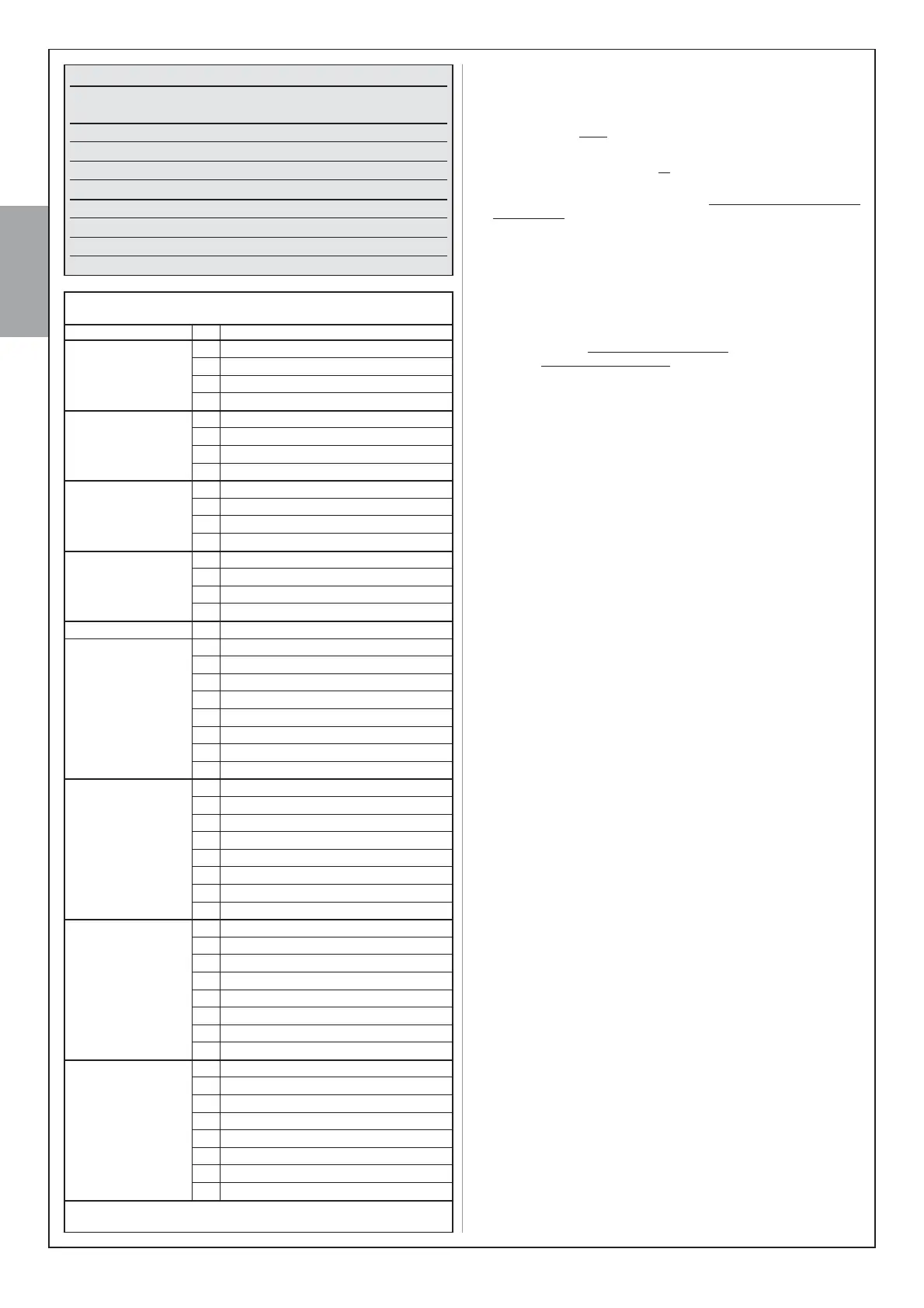
Table 9
Pause Time T1 + T2 T1
Pass door T1 + T2 T2
Motor force T1 + T2 T3
“Step-by-Step” function T1 + T2 T4
Discharge on Closure (motor 1) T1 + T3 T1
Discharge on Opening (motor 1) T1 + T3 T2
Discharge on Closure (motor 2) T1 + T3 T3
Discharge on Opening (motor 2) T1 + T3 T4
Access
keys
Parameter
Key for
display
Table 10
Parameter N. Set value
Pause Time 1 10 seconds
2 20 seconds (*)
3 40 seconds
80 seconds
“Pedestrian” 1 Opening of 1 leaf to mid-travel
command 2 Total opening of 1 leaf (*)
3 Partial opening of 2 leafs to 1/4 of travel
Partial opening of 2 leafs to mid-travel
Motor force 1 Minimum
2 Medium low (*)
3 Medium high
Maximum
“Step-by-Step” 1 Open > Stop > Close > Stop > ...
command 2 > Open > Stop > Close > ... (*)
3 > Open > Close > ...
> Open > ...
Pressure discharge
• on Closure 1 No discharge (*)
(motor 1) 2 0,1s (Minimum)
3 ••
•••
5 0,4s (Medium)
6 •••••
7 ••••••
8 0,7s (Maximum)
• on Opening 1 No discharge (*)
(motor 1) 2 0,1s (Minimum)
3 ••
•••
5 0,4s (Medium)
6 •••••
7 ••••••
8 0,7s (Maximum)
• on Closure 1 No discharge (*)
(motor 2) 2 0,1s (Minimum)
3 ••
•••
5 0,4s (Medium)
6 •••••
7 ••••••
8 0,7s (Maximum)
• on Opening 1 No discharge (*)
(motore 2) 2 0,1s (Minimum)
3 ••
•••
5 0,4s (Medium)
6 •••••
7 ••••••
8 0,7s (Maximum)
Factory setting