4 – ENGLISH
2.1 LIST OF CONSTITUENT PARTS
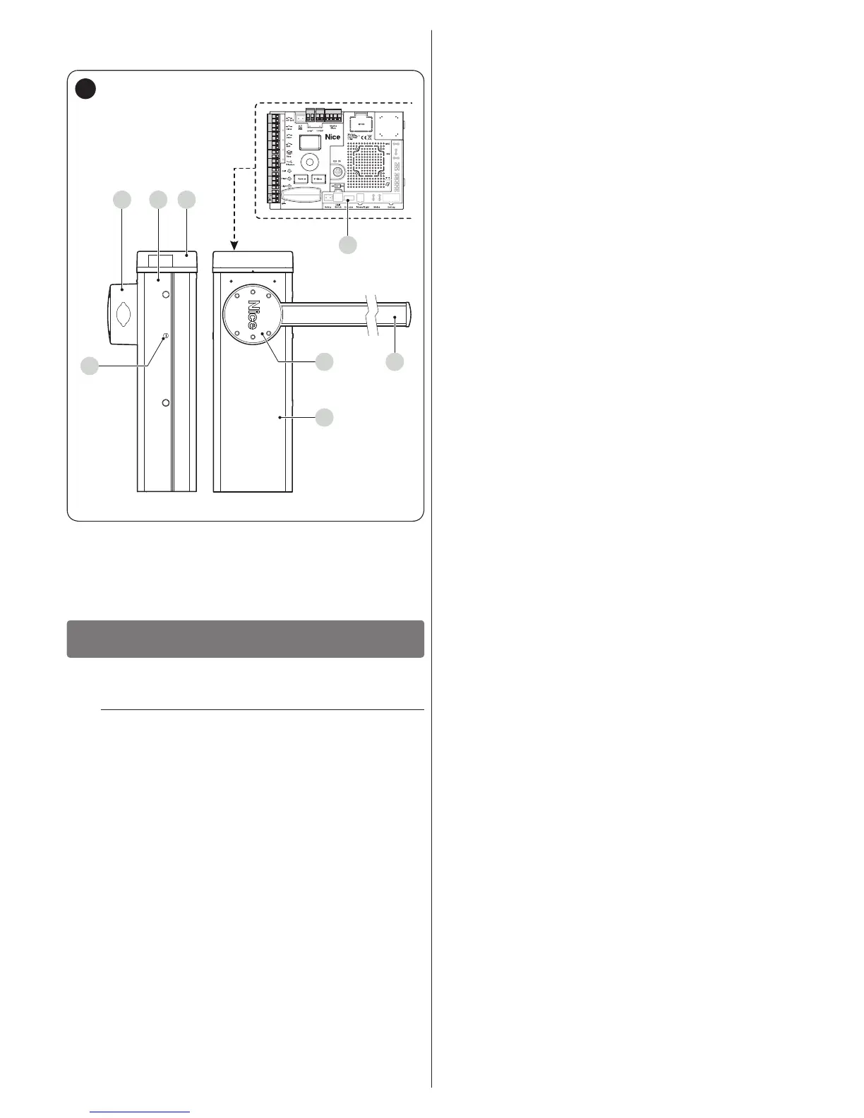
“Figure 1” shows the main parts making up the M/L-BAR.
C
EA
B
BA
F
OGI
Bluebus
Stop SbS Open Close
HPSbS
FlashLight
Loop1
Master/Slave
Loop2
D
1
A Boom support
B Gearmotor containment box
C Cover
D Electronic control and command unit
E Boom
F Locking/unlocking key
INSTALLATION
3
3 INSTALLATION
3.1 PRE-INSTALLATION CHECKS
a
The installation must be carried out by qualied
personnel in compliance with the current legisla-
tion, standards and regulations, and with the in-
structions provided in this manual.
Before proceeding with the product’s installation, it is necessary
to:
– check the integrity of the supply
– check that all the materials are in good working order and
suited to the intended use
– check whether it is possible to observe the operating limits
specied in the paragraph “Product usage limits“
– check that the installation location is compatible with the over-
all clearance of the product (see “Figure 3“)
– check that the surface chosen for installing the boom gate is
solid and can ensure stable anchorage
– make sure that the installation area is not subject to ooding; if
necessary, the product must be installed appropriately raised
above ground level
– check that the space surrounding the boom gate allows for
executing the manual manoeuvres easily and safely
– check that there are no obstacles along the boom’s path ca-
pable of hampering the opening and closing manoeuvres
– check that each device to be installed lies in a position that is
protected against the risk of accidental impact.
– verify that the mounting positions of the various devices are
protected against impacts and that the mounting surfaces are
sufciently sturdy
– prevent any parts of the automation from being immersed in
water or other liquids
– keep the product away from heat sources and open ames
and acid, saline or potentially explosive atmospheres; these
may damage the product and cause malfunctions or danger-
ous situations
– connect the control unit to an electricity supply line equipped
with a safety earthing system
3.2 PRODUCT USAGE LIMITS
Before proceeding with the product’s installation, it is necessary
to:
– check that all the values appearing in the “TECHNICAL SPEC-
IFICATIONS” chapter are compatible with the intended use
– check that the estimated durability (refer to the paragraph “
Product durability”) is compatible with the intended use
– check that all limitations, conditions and warnings appearing
in this manual can be fully observed.
3.2.1 Product durability
The product’s durability is its average economic life value and is
strongly inuenced by the degree of severity of the manoeuvres:
in other words, the sum of all factors that contribute to product
wear.
To estimate the durability of your automated device, proceed
as follows:
1. add the values of the items in “Table 2” relative to the
system’s conditions
2. in the graph shown in “Figure 2”, from the value obtained
above, trace a vertical line until it intersects the curve;
from this point trace a horizontal line until it intersects the
line of the “manoeuvre cycles”. The value obtained is the
estimated lifetime of your product.
The durability values shown in the graph can only be obtained if
the maintenance schedule is strictly observed – see the “PROD-
UCT MAINTENANCE” chapter. The durability is estimated on
the basis of the design calculations and the results of tests ef-
fected on prototypes. Being an estimate, therefore, it offers no
explicit guarantee of the product’s actual useful life.
Example of durability calculation: M5BAR with mobile sup-
port, level 3 speed and braking
“Table 2” shows the “severity indices” for this type of installation:
10% (“Mobile support”), 10% (“Level 3 speed”) e 10% (“Brak-
ing”).
These indicators must be added together to obtain the overall
severity index, which in this case is 30%. With the value calcu-
lated (30%), identify along the graph’s horizontal axis (“severity
index”) the value corresponding to the number of “manoeuvre
cycles” that the product can perform throughout its lifetime =
roughly 550.000 cycles.
 Loading...