ENGLISH – 7
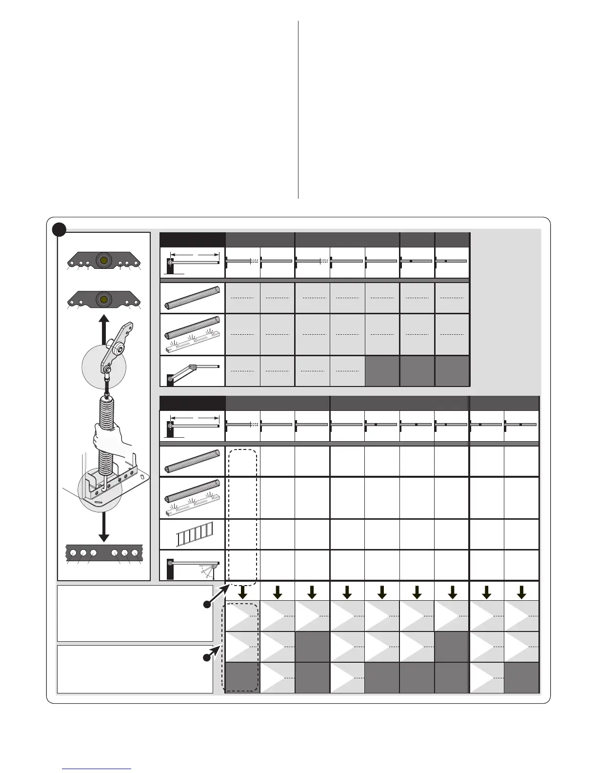
3.6 ADJUSTING THE BOOM GATE
The boom gate is factory-set in the following way:
– balancing spring fastened to the right, installation selector on
the right, anchored through non-permanent holes
– closing manoeuvre of the boom towards the left.
These are random settings, therefore the following checks must
be carried out to understand whether they must be changed:
– if a single accessory will be installed: identify in box “A”
in “Figure 6” your boom gate version, the length of the boom
and, lastly, the accessory you intend mounting on the boom;
with this data, read the corresponding letter and the number
relative to the holes to be chosen to attach the spring
– if multiple accessories will be installed: identify in box “B”
in “Figure 6” your boom gate version, the length of the boom
and, lastly, the type and number of accessories you wish to
mount on the boom; add the numbers in brackets linked to the
accessories and use the result of the addition to read, in the
lower part of box “B”, the letter and the number relative to the
holes to be chosen to attach the spring
– if the boom must close tot he right of the motor: the spring’s
attachment must be shifted to one of the holes located on the
other arm of the balancing lever.
M3BAR / M5BAR
M7BAR / L9BAR
3 2 1 321
B A BA
C B A CBA
XBA13
M3BAR
L9BAR
M7BAR
M5BAR
M3BAR
2,65 m 3,15 m 3,50 m 4,15 m 5,15 m 7,33 m 9,33 m
M7BAR
M5BAR
XBA15
+ XBA14
XBA5
(5,15m)
XBA14
(4,15m)
XBA14
(4,15m) – 0,65m
XBA15
(3,15m)
XBA15
(3,15m) – 0,50 m
XBA14
+ XBA5
A
WA13
WA12
XBA4 /
XBA6 / XBA18
XBA11
(0)
(1)
(1)
(5)
(0)
(1)
(1)
(4)
(0)
(1)
(2)
(4)
(0)
(1)
-
(4)
(0)
(1)
(1)
(3)
(0)
(1)
(1)
(3)
(0)
(1)
(2)
(3)
(0)
(1)
-
(3)
(0)
(1)
(2)
(3)
0÷1=
A
1
A
3
C
2
B
2
A
1
A
3
B
2
B
2
B
3
B
3
C
2
B
2
B
3
B
3
C
1
C
3
B
1
B
1
XBA13
XBA13
XBA4 /
XBA6 / XBA18
XBA13
?
M5BAR
L9BAR
M7BAR
M5BAR
3,50 m 4,15 m 5,15 m 5,15 m 5,00 m 6,33 m 7,33 m 7,33 m 8,33 m
M7BAR
XBA15
+ XBA14
XBA15
+ XBA14
XBA15
+ XBA15
XBA15+XBA15
(6,30m) –1,30m
XBA5
(5,15 m)
XBA5
(5,15 m)
XBA14
(4,15 m)
XBA14
(4,15m) – 0,65m
XBA14
+ XBA14
B
?
2÷7=
0÷1=
2÷4=
5÷6=
0 ÷ 2 =
3 ÷ 5 =
6 ÷ 7 =
0÷2 =
3÷5 =
0÷2=
3÷5=
0÷2=
3÷4=
5÷6=
0 ÷ 2 =
3 ÷ 6 =
B
2
B
3
B
3
4 ÷ 5 =
C
2
C
1
C
2
A
2
A
2
A
3
B
1
B
2
B
1
3 ÷ 4 =
B
3
B
2
A
1
A
2
A
3
A
3
B
1
L9BAR
L9BAR
6
1. Add the numbers between
brackets, present in the col-
umn, choosing only among
those linked to the installed
accessories.
2. Use the result of the addition
to determine the number of
holes required to attach the
spring.
 Loading...