TABLE 17
Perimeter of the loop Number of turns to be carried out
2 – 4 m 6
4 – 7 m 5
7 – 12 m 4
more than 12 m 3
Note – If in the loop positioning place, below the floor, there are some metal
reinforcements, the inductivity of the loop is reduced. In this case, it is
necessary to add 2 turns to the twisting of the cable
EN
English – 17
able sheath. The length of the twisted cable must be less than 20 m.
01. After determining the size of the loop, dig a groove in the floor of a width =
8 mm and a depth = 30-50 mm (fig. H);
02. Clean the groove and insert the loop, trying to compact it in a way to avoid
it moving;
03. Carry out the number of turns of the loop depending on the perimeter, as
indicated in Table 17: use a 1.5 mm
2
unipolar isolated copper cable (fig. H);
04. Before sealing the groove, check that the value of the inductive loop is
between 100 and 400 uH or, through the Oview programmer, check that
the value of the measured frequency (Parameter “Loop Frequency”) is
between 30 and100 KHz;
05. Cover the loop with sand to protect it and then seal the groove with bitu-
men or resin for outdoor use (fig. H). Important! – The temperature of the
sealant must not exceed the maximum temperature admitted for the isola-
tion of the cable, otherwise a loss in isolation towards the earth may occur.
TABLE 15
Function Values Default
Loop 1 sensitivity 10 – 100% 90%
Loop 2 sensitivity 10 – 100% 90%
Loop power supply on – off on
Loop 1 active on – off on
Loop 2 active on – off on
Loop 1 operating mode 1 – 5 1
Loop 2 operating mode 1 – 5 1
Loop 1 permanence time 2 – 20 = always 20 = always
Loop 2 permanence time 2 – 20 = always 20 = always
Output function 1, 2, 3:
Active out (1,2,3) for loop 1 selectable off
Output function 1, 2, 3:
Active out (1,2,3) for loop 2 selectable off
Calibration [also carried out upon start-up] on – off
Loop 1 activation mode*: 1 – 5 1
Loop 1 time 0 – 25 s 2s
Loop 2 activation mode*: 1 – 5 1
Loop 2 time 0 – 25 s 2s
Loop 1 frequency display 0 - 127000 -
Loop 2 frequency display 0 - 127000 -
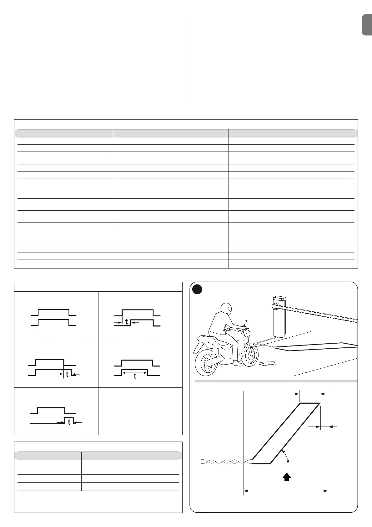
G
approximately 0,8 m
Direction of travel
0,2 m
Route
45°
06. The electric cables must be connected to the Loop1 (fig. I) and Loop2
(fig. L) terminals. The Loop2 terminal presents 2 connection possibilities
(fig. L); based on the type of connection used, it varies the working fre-
quency of the loop.
Important! – If Loop1 is positioned near Loop2 and both work at the
same frequency (or almost), interference could be generated; in this case,
it is necessary to change the connection to Loop2 terminal.
TABLE 16
1
loop
relay
loop
relay
loop
relay
loop
relay
loop
relay
2
34
5