4 – English
EN
3.3 - Typical system
Fig. 3 shows the components in the product pack:
[a] - road barrier with built-in control unit
[b] - pole support and cover
[c] - 2 boxes for photocells
[d] - 4 half-shells for pole insertion
[e] - Fixed pole plug; 2 insertions per impact protection rubber; 2 insertions
without impact protection rubber
[f] - keys for manual locking and release of the pole; keys for locking the
cover; metal hardware (screws, washers, etc.)
[g] - foundation plate
[h] - 4 fixing bolts
04. Loosen the bolt that fixes the rod end to the balancing lever (fig. 11 -
phase b);
05. Detach the bolt from the lower connection plate of the spring (fig. 11 -
phase c);
06. Release the gearmotor (fig. 7): refer to paragraph 3.6;
07. Turn the balancing lever by 90° (fig. 8);
08. Identify the hole where to fix the spring on both the balancing lever and the
lower plate: see table 4;
09. Hook the bolt to the lower plate and then lock the rod end on the balanc-
ing lever through close tightening (fig. 12);
10. Lock the gearmotor (fig. 10): refer to paragraph 3.6.
3.3.2 - Identification of the spring anchoring holes
To identify the holes to be used to anchor the spring, in correspondence to the
accessories to be used in the system, we recommend using Table 4 to quick-
ly find the correct hole.
In Table 4, in correspondence to the “pole length” of your barrier, find the
accessories to be used, add them and check the result in item “position of the
spring anchoring hole”. The key explains, based on the length of the barrier, the
meaning of the letters (A, B, C) and the numbers (1, 2, 3)
NOTE – For single use of the following accessories: Rubber, Lights with pole
long up to 3 m and for the Pivot Pole long up to 4 m, check the result directly in
the item of the same accessory.
TABLE 3 - Technical specifications of electrical cables (Fig. 1)
Fig. 1, shows an example of an automation system set up with Nice compo-
nents. With reference to the typical standard layout fig. 1, locate the approxi-
mate position for installation of each component envisaged in the system.
IMPORTANT! – In general, position the ends of the ducting used for
electrical cables in the vicinity of the points envisaged for fixture of the
various components. Note: The ducting serves to protect electric cables
and prevent accidental damage, such as in the case of impact.
The barrier is factory set for the closing manoeuvre to the left; in this
phase, it is important to decide whether the opening direction of the pole is to
be inverted. If Closure to the right is required, see paragraph 3.3.1.
Prepare the electrical cables needed for your system, referring to fig. 1 and
“Table 3 - Technical characteristics of electrical cables”.
3.3.1 - Modifying the factory settings of the Closure manoeuvre
If Closure to the right
is required, proceed as follows:
• MBAR Version:
01. Remove the cover (fig. 4);
02. Loosen the 2 screws fixing the cabinet door (fig. 5);
03. Manually turn the balancing screw (fig. 6 - phase a and b) so that there is
no power;
04. Loosen the spring lock bolt and manually turn the balancing screw (fig. 6 -
phase a and b) so that there is no power;
05. Detach the bolt from the lower connection plate of the spring (fig. 6 -
phase d);
06. Release the gearmotor (fig. 7): refer to paragraph 3.6;
07. Turn the balancing lever by 90° (fig. 8);
08. Identify the hole where to fix the spring on both the balancing lever and the
lower plate: see paragraph 3.3.2, table 4 and figure;
09. Hook the bolt to the lower plate and then lock the rod end on the balanc-
ing lever through close tightening (fig. 9);
10. Lock the gearmotor (fig. 10): refer to paragraph 3.6.
LBAR Version:
01. Remove the cover (fig. 4);
02. Loosen the 2 screws fixing the cabinet door (fig. 5);
03. Turn the tensioning nut of the springs (fig. 11 - phase a);
Connection Cable type Maximum admissible length
A: mains power supply cable 3 x 1,5 mm
2
30 m (note 1)
B: BlueBus cable 2 x 0,5 mm
2
20 m (note 2)
C: key-operated selector switch cable 2 cables 2 x 0,25 mm
2
(note 3) 30 m
Input cable Open 2 x 0,25 mm
2
30 m
Input cable Close 2 x 0,25 mm
2
30 m
Flashing light cable (note 4) 2 x 0,5 mm
2
30 m
with aerial RG58 shielded type 15 m (less than 5 m recommended)
Pole indicator cable Open (note 4) 2 x 0,5 mm
2
30 m
Pole lights (note 4) --
Loop Detector Cable 1 x 1,5 mm
2
twisted (note 5) 20 m twisted (note 5)
Master/Slave Cable 3 x 0,5 mm
2
20 m
IMPORTANT! – The cables used must be suited to the installation environment.
Note 1 – If the power cable is longer than 30 m, a cable with a larger cross-section is required (3x2.5 mm
2
) and safety earthing is necessary in the vicinity of
the automation.
Note 2 – If the BlueBus cable is longer than 20 m, up to a maximum of 40 m, a cable with a larger cross-section is required (2x1 mm
2
).
Note 3 – These 2 cables may be replaced by a single cable 4x0.5 mm
2
.
Note 4 – Before making the connection, check that the output is programmed for the device to be connected (see paragraph 6.2 - Table 8).
Note 5 – Shorten the two ends coming out of the loop, with at least 20 turns per metre.
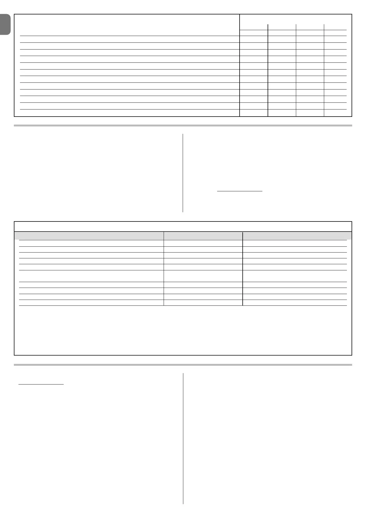
TABLE 2 Severity Index
M3BAR M5BAR M7BAR LBAR
Pivot Pole (XBA12) 20 15 - -
Speed level 3 15 10 15 15
Speed level 2 0 0 10 10
Interruption of manoeuvre via Foto > 10% 15 10 15 15
Interruption of manoeuvre via Alt > 10% 10 10 15 15
Mobile support (XBA11) - 101010
Braking 10 10 10 10
Force equal to 7 or 8 10 10 10 10
Force equal to 5 or 6 5 555
Presence of saline mist 10 10 10 10
Presence of dust or sand 5 555
Rack - 555
Room temperature higher than 40° and lower than 0° C 5 5 5 5