EN
18 – English
7.6 - Master - Slave mode
This operating mode is used if it is necessary to automate 2 counterposed bar-
riers which perform synchronised movements. In this mode, a barrier works as
Master and commands the manoeuvres, while the second works as Slave and
carries out the commands sent from the Master barrier; by default all the barri-
ers are set as Master.
To configure the barrier as Slave it is necessary to activate the level 1 function
“Slave Mode” (see Table 7).
The connection between Master and Slave takes place through the BusT4 with
the dedicated Master/Slave connector.
Important! – Should the Oview programmer be used, it is necessary to
modify the parameter “Together” or “Address” of one of the 2 barriers.
This is to avoid the simultaneous communication of the 2 control units
with the Oview programmer.
7.6.1 - Installation and electrical connections
Warnings
• All the devices, including the radio receiver, must be connected on the Master
barrier;
• If the buffer battery is used, each barrier must have its own;
• In the Slave barrier it is possible to carry out the following connections:
- its own flashing light (Flash)
- its own Pole Open Indicator (S.C.A.)
- pole lights
- its own sensitive edge (Stop)
- its own command device (P.P.), which commands the total opening of
the Slave pole only
- the Open and Close inputs are not used
- the Loop1 and Loop2 inputs programmed with “Open” mode
- the receiving radio
To install 2 barriers and program them with “Master - Slave” mode, proceed as
follows:
01. Install the 2 barriers (fig. M).
It is not important which of the two works as Master or Slave; it is neces-
sary to assess the convenience to create the electrical connections and
that the “Step-Step” command that will carry out the Slave barrier will pro-
vide the total open of the Slave pole only;
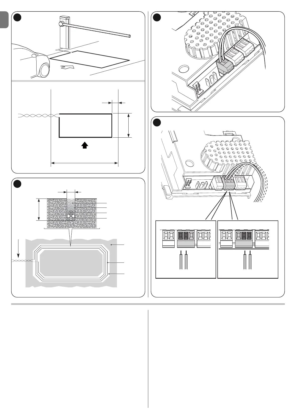
02. Connect the two control units one to the other through the Master/Slave
connector (fig. 54), respecting the polarity indicated;
03. At this point, carry out the other electrical connections (fig. 54), referring to
the indications contained in chapter 4 - Electrical connections;
H
5 mm - 8 mm
Sealant
Groove
String
Loop
(the cable
must be inser-
ted in the
groove)
Connection
(twisted cable)
Groove
5 - 8 mm
Earth
Twisted cable
I
L
F
approximately 0,35 m
Direction of travel
LOOP1 LOOP2 LOOP1 LOOP2
Route
1 m
30 mm -
50 mm