English – 5
EN
3.4 - Barrier lift fixture
3.4.1 - If the support surface already exists
01. Open the cabinet of the barrier (fig. 13);
02. Place the barrier on the fixing surface and trace the points where the slots
are to be fixed (fig. 14);
03. Move the barrier and drill the traced surface points; then insert 4 expansion
bolts, not supplied (fig. 15);
04. Position the barrier correctly and secure by means of the relative nuts and
washers not supplied (fig. 16).
3.4.2 - If the support surface does not exist
01. Dig the foundation pit (*) to house the foundation plate;
02. Prepare ducting for connection cables (fig. 17);
03. On the foundation plate, fix the 4 bolts, placing a nut on the upper side of
each and one on the lower side of the plate (fig. 17). Caution – The lower
nut must be tightened down to the threaded section;
04. Now cast the concrete, and before it sets, embed the foundation plate,
which must be positioned flush with the surface, parallel to the pole and
perfectly level (fig. 17). Wait for the concrete to set completely; in general,
at least 2 weeks;
05. Remove the 4 upper nuts of the bolts;
06. Open the cabinet of the barrier (fig. 18);
07. Position the barrier correctly and secure it by means of the relative nuts
and washers supplied with the foundation plate and removed in point 04
(fig. 19).
(*) Note - The fixing surface must be perfectly smooth and flat. If the surface is
in concrete, it must be at least 0.15 m thick, and must be adequately reinforced
with steel cages. The concrete volume must be greater than 0.2 m
3
(a thick-
ness of 0.25 m corresponds to 0.8 m
2
; in other words equal to a square base
of approx. 0.9 m per side). Anchoring to the concrete can be by means of 4
expansion bolts, fitted with 12 MA screws, which resist to a traction load of at
least 400 Kg. If the fixing surface is in another material, the consistency must be
checked and ensure that the 4 anchoring points can resist a load of at least
1000 Kg. For fixture, use 12 MA screws.
3.5 - Pole installation
3.5.1 - Pole support assembly
01. Insert the two plugs in the relative seats on the output motor shaft (fig. 20);
02. Position the support on the output motor shaft, placing it in the “vertical
pole” position and tighten the relative screws and washers fully down to
secure (fig. 21);
03. Position the pole cover and partially secure
by means of the 6 screws sup-
plied (fig. 22).
3.5.2 - Pole assembly (3 metres / 5 metres)
01. Assemble the two pole insertions (fig. 23);
02. Insert, from the same end of the pole, the insertions just assembled. Use a
rubber mallet (fig. 24);
03. Lightly grease the aluminium guide on both sides (fig. 25);
08. Perform this operation on both ends of the pole: insert the first part of impact
protection rubber in the slot, through to the end of the pole; then insert the
joint for the impact protection rubber (fig. 26) and repeat with all parts;
09. The impact protection rubber may protrude by about 1 cm from the end of
the profile (fig. 27):
A) position the pole plug and lock it with the two screws (fig. 28);
B) position and block the two rubber cover plugs (fig. 28);
10. Insert the pole assembly in the pole support shell, pushing it up to the end
and then tighten the 6 previously inserted support screws fully down (fig. 29).
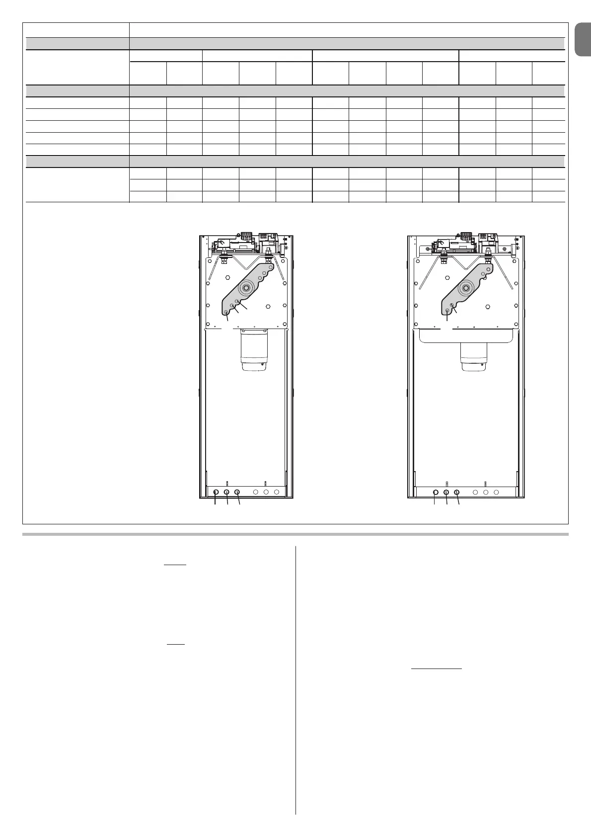
TABLE 4
LENGTH OF THE POLE
M3BAR M5BAR M7BAR LBAR
2,65 m 3,15 m 3,5 m 4,15 m 5,15 m 5,15 m 5 m, 6,33 m 7,33 m 7,33 m 8,33 m 9,33 m
entire entire with joint
ACCESSORIES
XBA13 - Rubber A1 A3 0 0 C2 0 0 0 B2 0 0 B1
XBA4/XBA6/XBA18 - Lights A1 A3 1 1 C2 1 1 1 B2 1 1 B1
WA13 - Rack - - 1 1 - 2 1 1 - 2 2 -
WA12 - Mobile support - - 5 4 - 4 3 3 - 3 3 -
XBA11 - Pivot Pole B3 B3 C1 C3 - - - - - - - -
POSITION OF THE SPRING ANCHORING HOLE
0÷1 = B2 0÷1 = B3 0÷2 = A2 0÷2 = B1 0÷2 = A1 0÷2 = A3
2÷7 = B3 2÷4 = C1 3÷5 = A2 3÷5 = B2 3÷4 = A2 3÷6 = B1
5÷6 = C2 6÷7 = A3 5÷6 = A3
Example:
M5BAR with 4m pole + Rack
(1piece) (value:1) + Pole lights
(value:1) = Sum of values: 2
Risult = POSITION C1
A
M3BAR / M5BAR M7BAR / LBAR
123
B
C
123
A
B