EasyManua.ls Logo

Nice Pop PP7224

Default Icon
31 pages
To Next Page IconTo Next Page
Loading...
For swing gates with leaves
up to 2 m, also with large
posts and lightweight
structures.
Version compatible with
the solar power system Solemyo.
Sophisticated electronics: slowdown,
obstacle detection system, can be linked
to the 8.2 KOhm resistive sensitive edge.
User-friendly: release with personalised
key designed.
Sturdy, aluminium, anti-shearing arm.
Always ready for use: continues to work
even during power failures using optional
(PS124) batteries that fit inside the motor.
Exclusive functions: photo-test,
pedestrian gate, programmable input
for functions such as open, close,
photo2, open pedestrian and open partially.
Extra-small, shockproof body
with aluminium base.
Max.
Max. 250 mm
Min. 500 mm (90°)
Technical specifications
Power (Vac 50 Hz)
Emergency power supply
Current absorbed (line) (A)
Power absorbed (W)
Protection level (IP)
Torque (Nm)
Speed (Rpm)
Opening time (s)
Working temp. (°C Min/Max)
Insulation class
Work cycle (%)
Dimension (mm)
Weight (kg)
* version without control unit
230 -
PS124
~1 3
75
44
180
1.26-1.68
10
-20 ÷ +50
1B
30
167x315x254
21.6
PP7024 PP7224*
1 1,5 2
250
200
Max. gate length (m)
Max. gate weight (kg)
The shape, the height of the gate
and the weather conditions
can considerably reduce the values
shown in the graph to the side.
Dimensions
Utilisation limits
PopKit
167 mm
545
315
254
20 SYSTEMS FOR SWING GATES KIT PRICES 2010

Other manuals for Nice Pop PP7224

Question and Answer IconNeed help?

Do you have a question about the Nice Pop PP7224 and is the answer not in the manual?

Nice Pop PP7224 Specifications

General IconGeneral
BrandNice
ModelPop PP7224
CategoryGate Opener
LanguageEnglish

Summary

Nice PopKit Product Overview and Specifications

Technical Specifications

Details power, current, torque, speed, protection level, and operating temperature.

Safety Warnings and Precautions

General Safety Instructions

Covers essential safety warnings for personal safety and product handling during installation and use.

Installation Safety Guidelines

Outlines precautions for installation, including avoiding liquids, heat sources, and unauthorized modifications.

Installation Procedures

Electrical Connections and Release

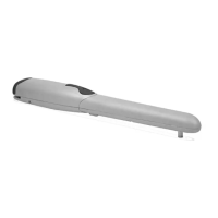
Explains releasing the gearmotor, securing the opening stop, and connecting power/batteries.

Testing, Maintenance, and Technical Data

POA1 Control Unit: Introduction and Safety

Product Description

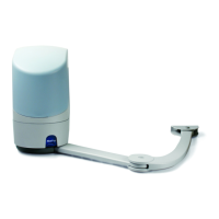
Introduces the POA1 control unit for POP 24V electromechanical actuators for swing gates.

Safety Warnings and Precautions

Highlights critical safety information for the POA1 control unit's installation and use.

POA1 Control Unit: Installation Setup

Electrical Connections and Notes

Provides detailed wiring diagrams, terminal explanations, and notes for various connections.

POA1 Control Unit: Wiring and Limit Switches

Automatic Limit Switch Search

Details the procedure for setting the mechanical limit switches for gate movement.

POA1 Control Unit: Testing and Diagnostics

Testing and Commissioning

Describes the essential phases for setting up automation for maximum system safety and compliance.

POA1 Control Unit: Programming Functions

Programmable Function Settings

Details how to program various functions and parameters for customized automation behavior.

POA1 Control Unit: Programming Examples

POA1 Control Unit: Programming Diagram

Complete Programming Workflow

Presents a comprehensive diagram illustrating the programming functions and parameter settings.

Accessories, Troubleshooting, and Maintenance

Troubleshooting Common Issues

Provides guidance for diagnosing and resolving common problems with the automation system.

Technical Product Specifications and Compliance

EC Declaration of Conformity

Presents the official EC declaration confirming the product's compliance with relevant directives.

Control Unit Wiring Diagrams

Energy Saving Connection

Diagram showing how to connect the control unit with the 'Everything in stand by' active mode.

Control Unit Wiring and Input Configurations

Connection without Energy Saving

Diagram showing connection without 'Everything in stand by' mode, utilizing the 'Phototest' function.

Related product manuals