English – 17
8
FURTHER DETAILS
8.1 - Adding or removing devices
You can add or remove devices at any timee.
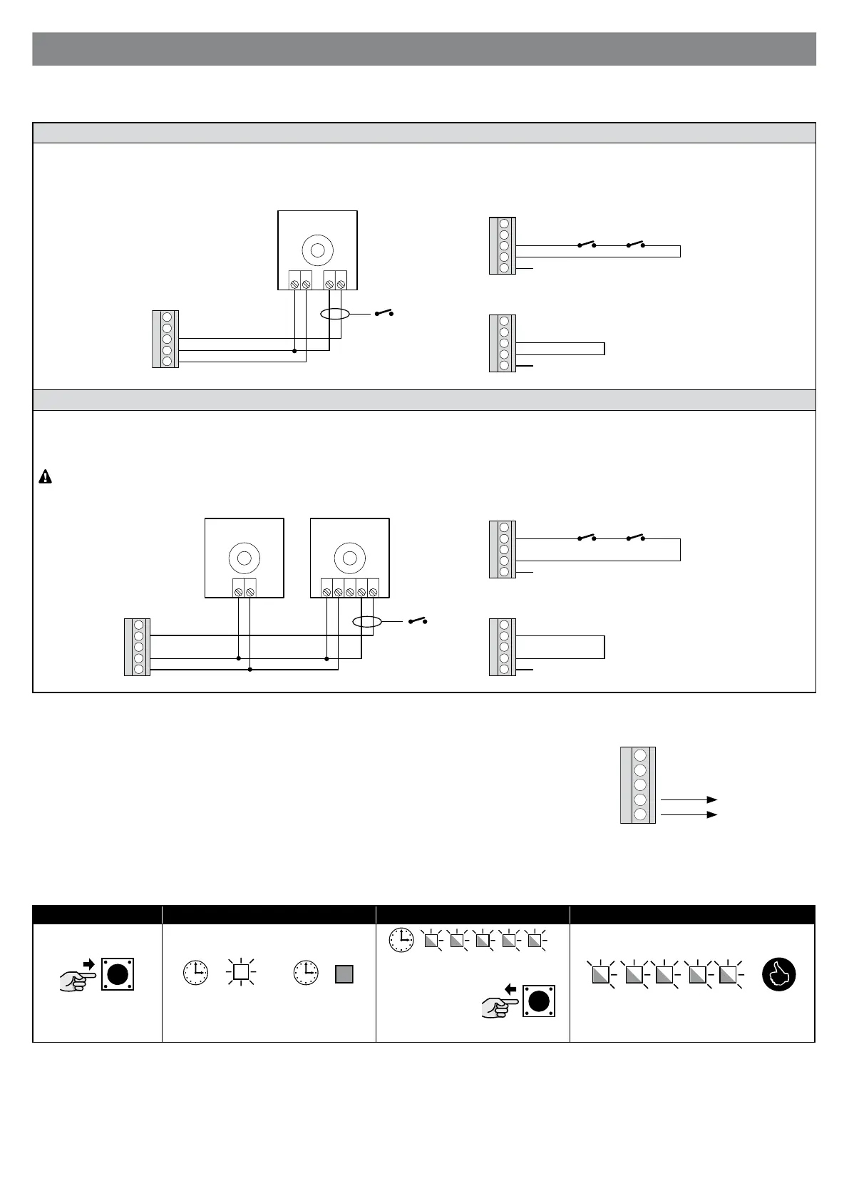
STOP input
Input that stops movement immediately, followed by a brief reverse of the manoeuvre.
You may connect devices with NC contacts to this input; multiple devices can be connected in series.
N.B.: when the NC contact opens, the automation stops and reverses its direction briey.
STOP
8910 11 12
8910 11 128910 11 12
Photocells
To add a pair of photocells, proceed as follows:
01. Power up the receivers (RX) via terminals 8 - 9
02. Connect the receiver’s NC contact in series with the NC contact already connected to control unit terminals 9 - 11.
If using two pairs of photocells, to prevent them interfering with each other, activate the synchronisation function described in the respective
user manual.
TX
1 2
RX
21 543
8910 11 12
8910 11 128910 11 12
8.2 - Power for external devices
To power external devices (transponder badge reader, or backlighting for a keyswitch) connect the device
to the control unit as shown in the gure.
The power supply voltage is 24Vac -20% ÷ +30% with a maximum available current of 100mA.
24 Vac (30 Vac max)
0
8910 11 12
8.3 - Total deletion of the receiver’s memory
To cancel all memorised transmitters or all data in the receiver’s memory, proceed as follows:
01. 02. 03. 04.
↕
RADIO KEY RADIO LED RADIO LED RADIO KEY AND LED RADIO KEY AND LED
8.4 - Diagnostics
Some devices are display messages to identify their status and faults.
8.4.1 - Control unit signals
The leds on the control unit issue signals to indicate their normal/faulty operation.
Table 10 lists the signals: