ENGLISH – 25
FURTHER INFORMATION
(Accessories)
9
9 FURTHER DETAILS (Accessories)
9.1 MODIFYING THE STOP INPUT
CONFIGURATION
STOP is the input that causes immediate stoppage of the ma-
noeuvre followed by its brief reversal. Devices with output fea-
turing normally open “NO” and normally closed “NC” contacts,
as well as devices with 8.2 kΩ xed resistor output, such as
sensitive edges, can be connected to this input.
As with the BlueBUS, the control unit recognises the type of
device connected to the STOP input during the learning phase
(see the “Device learning” paragraph); subsequently the con-
trol unit gives a STOP command when it detects a variation with
respect to the learned status.
Multiple devices, even of different types, can be connected to
the STOP input if suitable arrangements are made:
– Any number of NO devices can be connected to each other
in parallel.
– Any number of NC devices can be connected to each other
in series.
– Two devices with 8.2 kΩ xed resistor output can be connect-
ed in parallel; if there are more than 2 devices then they must
all be connected in cascade, with a single 8.2 kΩ terminating
resistor.
– It is possible to combine two NO and NC contacts by placing
them in parallel, while also mounting a 8.2 kΩ resistor in series
with the NC contact (this also allows for combining 3 devices:
NA, NC and 8.2 kΩ).
a
If the STOP input is used to connect devices with
safety functions, only those devices with 8.2 kΩ
xed resistor guarantee Category 3 safety against
faults in accordance with the EN 13849-1 standard.
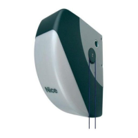
9.2 CONNECTING AN SM-TYPE RADIO RECEIVER
The control unit has a slot for mounting radio receivers with SM
connector (optional accessories) belonging to the SMXI, SMXIS,
OXI, etc. families, which can be used to remotely control the
control unit through transmitters that intervene on the control
unit’s inputs.
f
Before installing a receiver, disconnect the power
supply to the control unit.
To install a receiver (“Figure 30”):
1. insert the receiver (A) in the appropriate slot (B) on the
control unit’s electronic board.
B
A
30
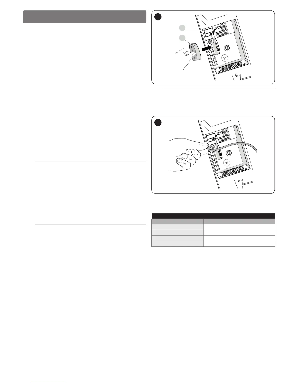
l
If the aerial incorporated in LUCYB or other type
of external aerial is not used, screw the rigid cable
supplied with the receiver onto the aerial terminal
(“Figure 31”):
31
The association between the radio receiver output and the com-
mand executed by the motor is shown in “Table 17”:
Table 17
SMXI / SMXIS
Receiver output Command
Output No. 1
“Step-by-Step”
Output No. 2
“Partial opening”
Output No. 3
“Open”
Output No. 4
“Close”
If the OXI radio receiver used in “EXTENDED MODE” is installed,
it may send the commands shown in “Table 18“.