4 – ENGLISH
INSTALLATION
3
3 INSTALLATION
3.1 PRE-INSTALLATION CHECKS
a
The installation must be carried out by qualied
personnel in compliance with the current legisla-
tion, standards and regulations, and with the in-
structions provided in this manual.
Before proceeding with the product’s installation, it is necessary
to:
– check the integrity of the supply
– check that all the materials are in good working order and
suited to the intended use
– make sure that the structure of the door is suitable for being
automated
– make sure that the characteristics of the door fall within the
operating limits specied in the “Product usage limits” par-
agraph
– verify that there are no points of greater friction during the
opening and closing movements along the entire door path
– verify that the area where the gearmotor is installed allows for
unlocking the latter and manoeuvring easily and safely
– verify that the mounting positions of the various devices are
protected against impacts and that the mounting surfaces are
sufciently sturdy
– prevent any parts of the automation from being immersed in
water or other liquids
– keep the product away from heat sources and open ames
and acid, saline or potentially explosive atmospheres; these
may damage the product and cause malfunctions or danger-
ous situations
– connect the control unit to an electricity supply line equipped
with a safety earthing system
– include a device on the electric power line ensuring complete
disconnection of the automation from the grid. The disconnec-
tion device must have contacts with a sufcient gap to ensure
complete disconnection, under the Category III overvoltage
conditions, in accordance with the installation instructions.
Should it be necessary, this device guarantees fast and safe
disconnection from the power supply; it must therefore be po-
sitioned in view of the automation. If placed in a non-visible
location, it must have a system that blocks any accidental on
unauthorised reconnection of the power supply, in order to
prevent dangerous situations. The disconnection device is not
supplied with the product.
3.2 PRODUCT USAGE LIMITS
The data relative to the product’s performances is included in
the “TECHNICAL SPECIFICATIONS” chapter and is the only
data that allows for properly assessing whether the product is
suitable for its intended use.
Check the application limits of SO2000 and of the accessories
to be installed, assessing whether their characteristics are ca-
pable of meeting the requirements of the environment and the
limitations specied below:
– the door dimensions must be below 20 m2
– the drive shaft must be compatible with the SO2000 output
and the relative keys supplied with the package
– the wall-mounting bracket must be sufciently long.
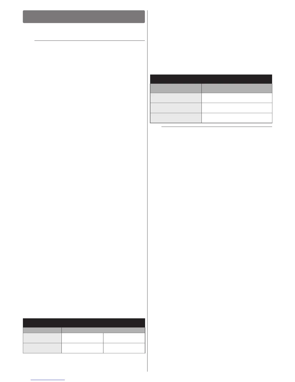
Table 1
SO2000 - LIMITATIONS OF USE IN RELATION TO THE TYPE OF
DOOR
Type of door Operating limits (m)
Protruding
overhead door
Max height 2.6 m Max length 3.0 m
Non-protruding
overhead door
Max height 2.6 m Max height 3.0 m
The measurements shown in “Table 1” are purely indicative and
are only needed for making a rough estimate. The actual suit-
ability of SO2000 for automating a specic door depends on
the degree of leaf balancing, guide friction and other aspects,
including occasional events such as wind pressure or the pres-
ence of frost, which could obstruct the leaf’s movement.
To determine the actual conditions, the force required to move
the leaf throughout its path must be measured, to ensure that
this value does not exceed the “rated torque” specied in the
“TECHNICAL SPECIFICATIONS” chapter; moreover, to calcu-
late the number of cycles/hour and consecutive cycles, it is im-
portant to consider the data shown in “Table 2”.
Table 2
SO2000 - LIMITS RELATING TO THE FORCE REQUIRED TO MOVE
THE DOOR LEAF
Force required to move the
leaf (N)
Maximum no. of cycles/hour
Maximum no. of consecutive cycles
Up to 120
20
35
120 ÷ 180
18
33
180 ÷ 220
15
30
a
The control unit is equipped with a manoeuvre lim-
iting device that prevents possible overheating; it is
based on the motor load and duration of the cycles,
and intervenes when the maximum limit is exceed-
ed.
3.2.1 Product durability
The product’s durability is its average economic life value and is
strongly inuenced by the degree of severity of the manoeuvres:
in other words, the sum of all factors that contribute to product
wear.
To estimate the durability of your automated device, proceed
as follows:
1. add the values of the items in “Table 3” relative to the
system’s conditions
2. in the graph shown in “Figure 2”, from the value obtained
above, trace a vertical line until it intersects the curve;
from this point trace a horizontal line until it intersects the
line of the “manoeuvre cycles”. The value obtained is the
estimated lifetime of your product.
The durability values shown in the graph can only be obtained if
the maintenance schedule is strictly observed – see the “PROD-
UCT MAINTENANCE” chapter. The durability is estimated on
the basis of the design calculations and the results of tests ef-
fected on prototypes. Being an estimate, therefore, it offers no
explicit guarantee of the product’s actual useful life.
Example of durability calculation: automation of a door
weighing 130 kg
“Table 3” shows the “severity indices” for this type of installation:
30% (“Weight of the door”), 20% (“Force required to move the
door”) and 10% (“Ambient temperature above 40°C or below
0°C or humidity above 80%”).
These indicators must be added together to obtain the overall
severity index, which in this case is 60%. With the value iden-
tied (60%), look at the horizontal axis of the graph (“severity
index”) and identify the value corresponding to the number of
“manoeuvre cycles” that the product can perform throughout its
lifetime – roughly 18,000 cycles.