Safety
information
Product
information
Mechanical
installation
Electrical
installation
Getting
started
Basic
parameters
Running
the motor
Optimization
EtherCAT
interface
SD Card
Operation
Onboard
PLC
Advanced
parameters
Diagnostics
UL listing
information
Digitax HD M753 Control User Guide 113
Issue Number: 3
9.18.25 Supported drive modes
This object provides information on the supported drive modes.
Table 9-72 Supported drive modes
9.19 Interpolated position mode
Interpolated position mode operates in RFC-A and RFC-S modes.
Table 9-73 lists the objects that are supported:
Table 9-73 Supported Interpolated position mode objects
When using one of the CiA402 positioning modes, Distributed Clocks
must be enabled. Failure to do so may result in the EtherCAT interface
going into the SAFEOPERATIONAL state.
9.19.1 0x60C0 Interpolation_sub-mode_select
Table 9-74 0x60C0 Interpolation_sub-mode_select
9.19.2 0x60C1 Interpolation_data_record
This object is used to specify the target position. Linear interpolation
is used to generate position demand values every 250 μs. The position
is specified in user-defined position units. The value is written into sub-
index 1.
Table 9-75 0x60C1 Interpolation_data_record
9.19.3 0x60C2 Interpolation_time_period
Table 9-76 Interpolation_time_period
The implementation of interpolated position mode allows synchronous
operation only, where a fixed, common interpolation interval is defined.
The time specified must always be an integer multiple of the control loop
cycle time. The time period index has a minimum value of -6 (i.e. the
smallest time unit will be microseconds), see Table 9-77 for more
information.
Table 9-77 Interpolation time period units
The time period is checked to ensure that it is an integer multiple of the
control loop cycle time. Only linear interpolation is currently supported,
this type inserts a delay of one interpolation time period.
The input buffer has a maximum size of 1 data record, and a data record
contains one position in profile-defined units. The buffer is a FIFO buffer.
On each interpolator time period, a value is read from this buffer. The
correct number of data points for a specific interpolation mode are stored
internally. When a new position command is loaded in, the oldest
position command in the data set is discarded.
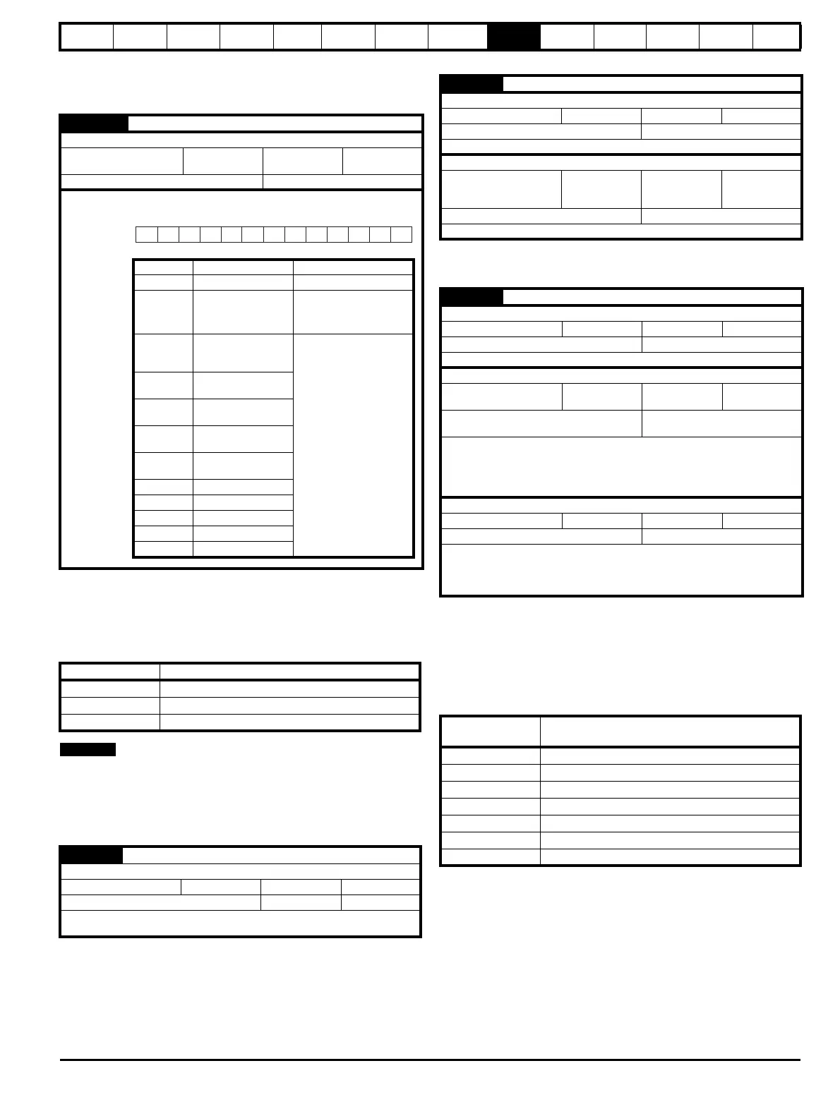
0x6502 Supported drive modes
Sub-index 0
Access: RO
Range: 0 to
0xFFFFFFFF
Size: 4 bytes Unit: N/A
Default: N/A Type: UDINT
Description:
Provides information on the supported drive modes as shown
below.
Index Name
0x60C0 interpolation_submode_select
0x60C1 interpolation_data_record
0x60C2 interpolation_time_period
0x60C0 Interpolation_sub-mode_select
Sub-index 0
Access: RW Range: 0 Size: 2 bytes Unit: N/A
Default: 0 (Linear interpolation) Type: INT
Description:
Specifies the interpolation type. At present the only supported
Interpolation Sub-Mode is ‘Linear Interpolation’.
31 16
ms
hm
r
tq
pv
vI
pp
cstca
cst
csv
csp
ip
r
15 11
10 9
8 7 6
5
4
3
2
1
0
Mnemonic Description Value
r Reserved 0
ms
Manufacturer specific
bits
0 = Function is not
supported
1 = Function is supported
cstca
Cyclic sync torque
mode with
communication angle
0 = Mode is not supported
1 = Mode is supported
cst
Cyclic sync torque
mode
csv
Cyclic sync velocity
mode
csp
Cyclic sync position
mode
ip
Interpolated position
mode
hm Homing mode
tq Torque profile mode
pv Profile velocity
vl Velocity mode
pp Profile position mode
0x60C1 Interpolation_data_record
Sub-index 0
Access: RO Range: N/A Size: 1 byte Unit: N/A
Default: 1 Type: USINT
Description: This object is used to specify the target position.
Sub-index 1
Access: RW
Range:
0x80000000 to
0x7FFFFFFF
Size: 4 bytes Unit: N/A
Default: N/A Type: DINT
Description: The set-point.
0x60C2 Interpolation_time_period
Sub-index 0
Access: RO Range: N/A Size: 1 byte Unit: N/A
Default: 2 Type: USINT
Description: The number of the last sub-index in this object.
Sub-index 1
Access: RW Range: 0 to 255 Size: 1 byte
Unit:
(sub-index 2)
Default:
250 (units are dependent on
the value in sub-index 2)
Type: USINT
Description:
The number of time units between interpolator re-starts. A time unit
is defined by sub-index 2. The interpolator time period value is
checked to ensure that it is valid. Valid values are 250 µs, 500 µs or
any multiple of 1 ms. An attempt to write other values results in an
SDO Abort code.
Sub-index 2
Access: RW Range: -6 to 0 Size: 1 byte Unit: N/A
Default: -6 (a time unit of 1 µs) Type: SINT
Description:
This specifies the time unit for the interpolation time period.
Sub-index 2 specifies the unit exponent. The time unit, therefore,
is 10
(sub-index 2)
. The range of values allows for the shortest time
unit to be 1 µs, and the longest to be 1 s.
Value in 0x60C2,
sub-index 2
Description
0 1 second
-1 0.1 of a second
-2 0.01 of a second
-3 0.001 of a second
-4 0.0001 of a second
-5 0.00001 of a second
-6 0.000001 of a second

 Loading...


