Safety
information
Product
information
Mechanical
installation
Electrical
installation
Getting
started
Basic
parameters
Running
the motor
Optimization
EtherCAT
interface
SD Card
Operation
Onboard
PLC
Advanced
parameters
Diagnostics
UL listing
information
Digitax HD M753 Control User Guide 223
Issue Number: 3
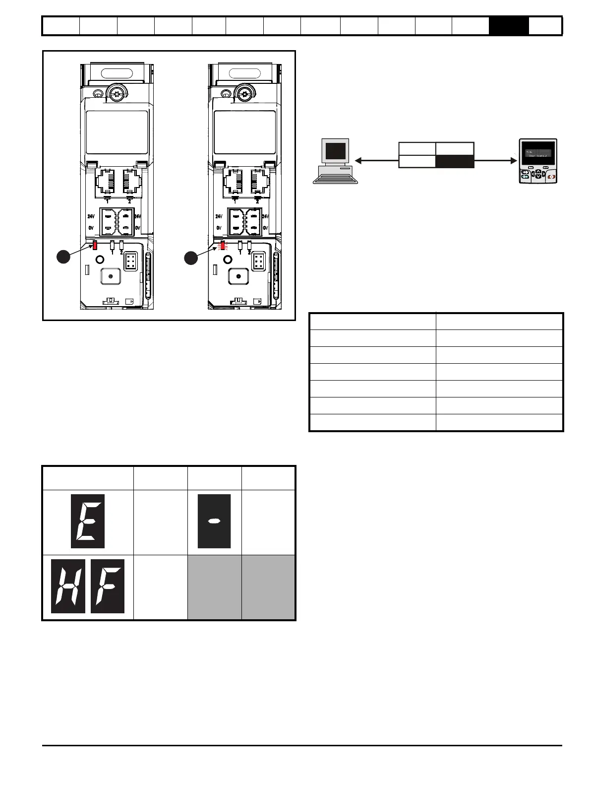
Figure 13-3 Location of the status LED
1. Non flashing: Normal status
2. Flashing: Trip status
13.2 Trip indications
The output of the drive is disabled under any trip condition so that the
drive stops controlling the motor. If the motor is running when the trip
occurs it will coast to a stop.
During a trip condition, where a KI-Compact Display is being used, a trip
or HF (hardware fault) condition is indicated as a scrolling message, with
an E prefix followed by a serial communications trip code and sub trip
code where relevant. Refer to Table 13-1 for further information.
Table 13-1 Trips associated with xxyzz sub-trip number
During a trip condition, where a KI-Remote Keypad is being used, the
upper row of the display indicates that a trip has occurred and the lower
row of the keypad display will display the trip string. Some trips have a
sub-trip number to provide additional information about the trip. If a trip
has a sub-trip number, the sub-trip number is flashed alternately with the
trip string unless there is space on the second row for both the trip string
and the sub-trip number in which case both the trip string and sub-trip
information is displayed separated by a decimal place.
If a display is not being used, the drive LED Status indicator will flash
with 0.5 s duty cycle if the drive has tripped. Refer to Figure 13-3.
Trips are listed alphabetically in Table 13-4 based on the trip indication
shown on the drive display. Alternatively, the drive status can be read in
Pr 10.001 'Drive OK' using communication protocols. The most recent
trip can be read in Pr 10.020 providing a trip number. It must be noted
that the hardware trips (HF01 to HF20) do not have trip numbers. The
trip number must be checked in Table 13-5 to identify the specific trip.
Example
1. Trip code 2 is read from Pr 10.020 via serial communications.
2. Checking Table 13-4 shows Trip 2 is an Over Volts trip.
3. Look up Over Volts in Table 13-4.
4. Perform checks detailed under Diagnosis.
13.3 Identifying a trip / trip source
Some trips only contain a trip string whereas some other trips have a trip
string along with a sub-trip number which provides the user with
additional information about the trip.
A trip can be generated from a control system or from a power system.
The sub-trip number associated with the trips listed in Table 13-2 is in
the form xxyzz and used to identify the source of the trip.
Table 13-2 Trips associated with xxyzz sub-trip number
The digits xx are 00 for a trip generated by the control system. For a
single drive (not part of a multi-power module drive), if the trip is related
to the power system then xx will have a value of 01, when displayed the
leading zeros are suppressed.
The y digit is used to identify the location of a trip which is generated by
a rectifier module connected to a power module (if xx is non zero). For a
control system trip (xx is zero), the y digit, where relevant is defined for
each trip. If not relevant, the y digit will have a value of zero.
The zz digits give the reason for the trip and are defined in each trip
description.
Display character Trip code Separator
Sub-trip
code
Range 1 to
254
Range 1 to
65535
Range 1 to
99
Over Volts OHt dc bus
OI ac Phase Loss
OI Brake Power Comms
PSU OI Snubber
OHt Inverter Temp Feedback
OHt Power Power Data
OHt Control
Comms
code
No. Trip
2
Over Volts

 Loading...


