Low byte
bit of
status data
Typically this data is returned
4)= 00h, 5)= 00h
Set speed data out of spec
Compressor stopped (waiting
for a valid start speed)
Start fail / Motor cable failure
4)= 01h, 5)= FFh
→ Compressor fail
4)= 02, 5)= FFh
→ Compressor fail
4)= 04h, 5)= FFh
→ Compressor fail
Wrong rotor position failure
4)= 08h, 5)= FFh
→ Compressor fail
4)= 10h, 5)= FFh
→ Inverter fail
4)= 20h, 5)= FFh
→ Compressor fail
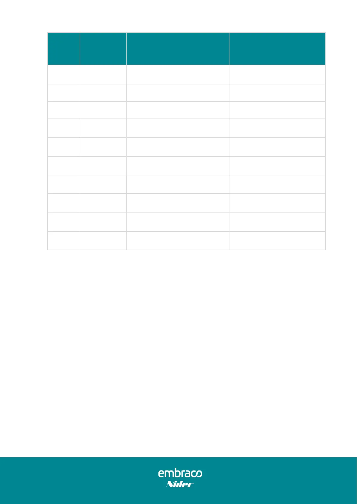
Table 20 – Serial Communication – Status Data
Note 1: When one or more errors occur, the corresponding bits are set to 1.
Example: Overload (0b00000010) and Under speed (0b00000100): 0xFF06
Note 2: The status data high byte defines the compressor state:
00xxh → compressor is running
FFxxh → compressor is stopped
4.2.4. Serial control connection and electrical schematic
The thermostat is connected to the Inverter through the CN209 connection, using the
Control Input Cable. Use the IN terminal for the Thermostat TX signal, the GND for the
Ground signal and the OUT terminal for the Thermostat RX signal (Figure 22).