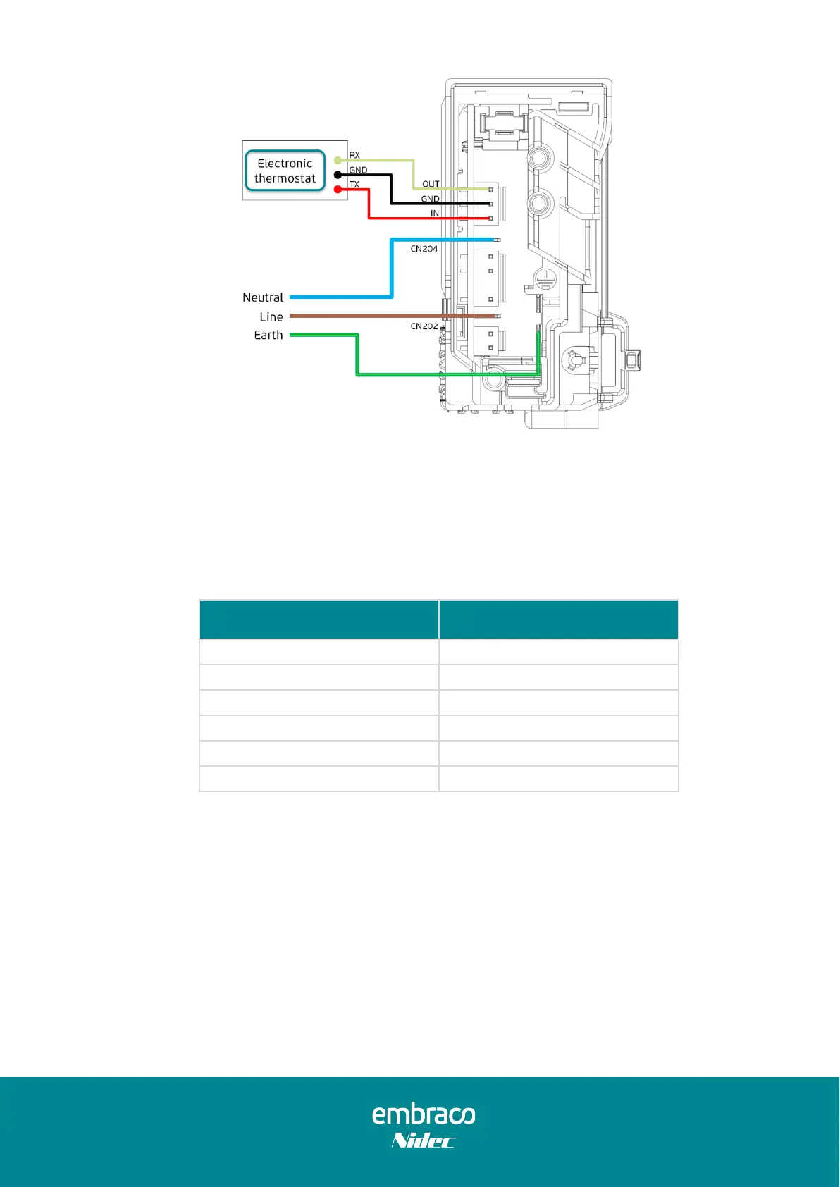
Figure 22 – Serial control connection
To guarantee serial communication's correct functionality, the signal sent to the Inverter
must be according to the following values (Table 21).
Table 21 – Serial input signal specification
The input resistance (R402) is 1,2 kΩ. The thermostat resistor connected to the Inverter TX
(Pin 1) must be designed considering a maximum current of 1,2 mA through the Inverter
optocoupler.
The circuit in Figure 23 shows the electrical connections to perform serial communication
between an electronic thermostat and CF01F-CF02F Inverter serial connector (CN209).