Unidrive M400 Step By Step Guide 5
Issue Number: 2
English
Français Deutsch Italiano Español
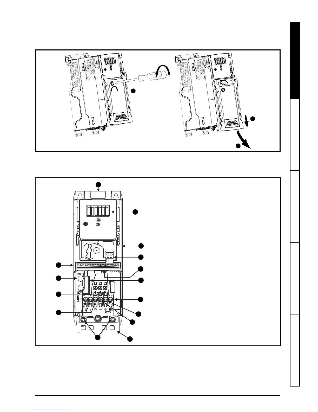
STEP 6: Remove the terminal cover
1. Using a flat bladed screwdriver, turn the terminal cover locking clip anti-clockwise by approximately 30°.
2. Slide the terminal cover down.
3. Remove terminal cover in direction shown.
STEP 7: Identify the features of the drive
Figure 7-1 Feature diagram (size 2 shown)
Key
1. Rating label (On side of drive)
2. Identification label
3. Option module connection
4. Relay connections
5. Control connections
6. Braking terminal
7. Internal EMC filter screw*
8. DC bus +
9. DC bus -
10. Motor connections
11. AC supply connections
12. Ground connections
13. Safe Torque Off connections
14. Cable bracket to screw onto ground
terminals (12).
15. Optional LCD Keypad location
* Before removing the screw, refer to section 4.7.2
in the Power Installation Guide.

 Loading...


