Unidrive M400 Step By Step Guide 7
Issue Number: 2
English
Français Deutsch Italiano Español
STEP 9: Wire the drive up
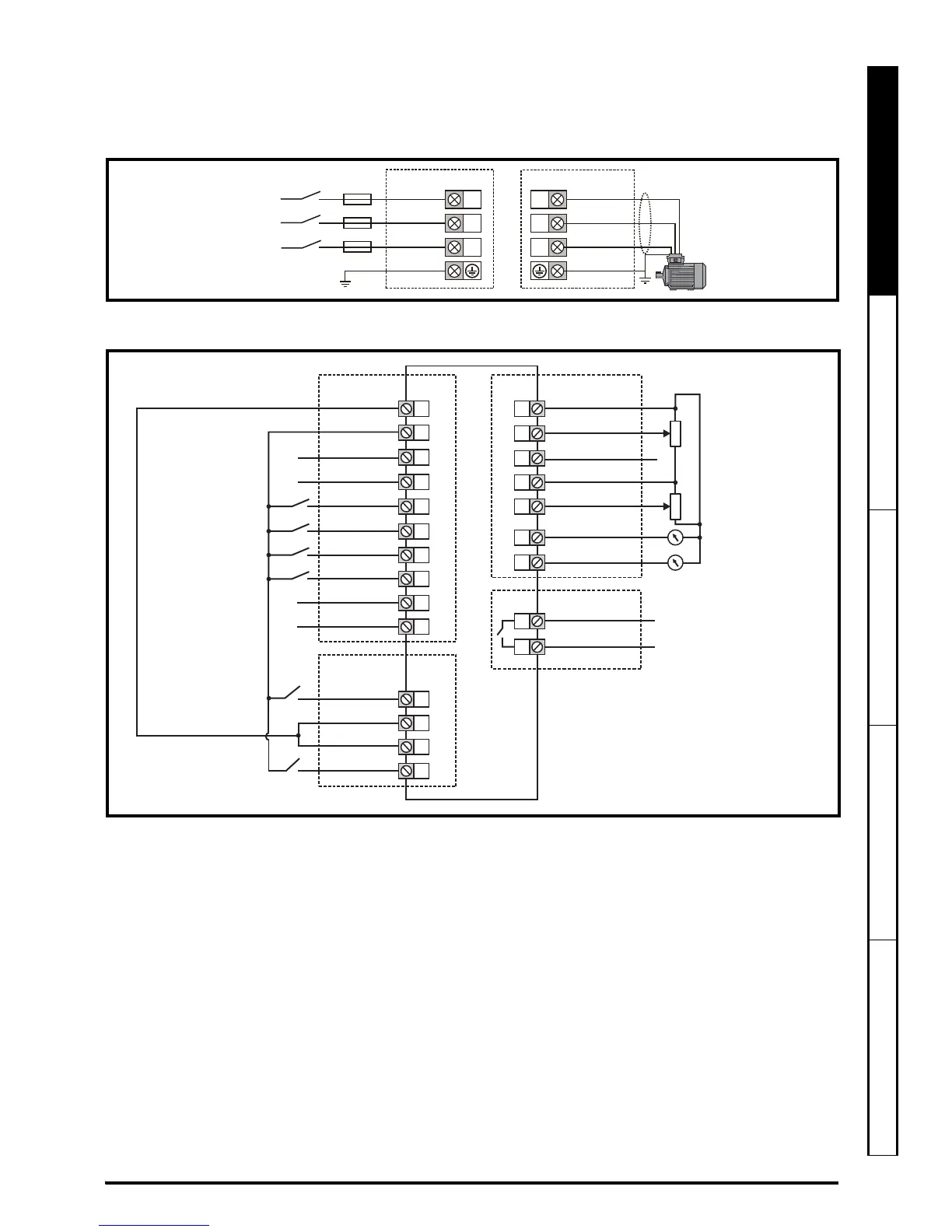
The wiring diagram is for use with the default drive configuration (Pr 00.005 set to AV) which is frequency control via
Analog Input 1 (0-10 V) or Analog Input 2 (0-10 V) selected by terminal 14.
Figure 9-1 Power terminal connections
* With a 1 ph supply, the supply should be connected to L1 and L3.
Figure 9-2 Unidrive M400 control terminal connections
** Unidrive M400 uses Safe Torque Off (drive enable) inputs and terminal 11 is unassigned.
*** 250 Vac maximum (UL class 1).
Refer to section 4.4 in the Quick Start Guide for information and wiring diagrams for alternative configurations.
An external braking resistor can be connected if required. Refer to section 4.5.1 in the Power Installation Guide
for further details.
STEP 10: Power up the drive
• Ensure the drive enable signal is not given (terminal 31 and 34) is open.
• Ensure the run signal is not given, terminal 12 and 13 are open.
• Ensure the motor is connected to the drive.
• Ensure the motor connection (Δ or Y) is correct.

 Loading...


