Chapter 3 Assembling
29
(4) Remove the two rubber caps from the fixing bolt
holes on the right front side of the intelligent
nosepiece (as viewed from the front). Insert the hex
driver (nominal designation: 4) into the holes and
firmly tighten the two zooming body fixing bolts. Afte
tightening the bolts, put the rubber caps back onto
the bolt holes.
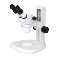
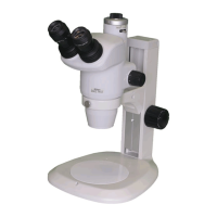
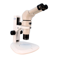
Attaching the zooming body
by tightening the bolts
Connecting signal cables
The signal cable for the SMZ25 comes from the left side of the zooming body. In case of the SMZ18, connect the
signal cable supplied with the SMZ18 to the round connector on the left side of the zooming body.
Connect the other end of the cable to the connector “ZOOM” on the motorized focus unit or relay box. (See “[4]
Connect signal cables.”)
4
Connect signal cables.
Connect the cables required for detecting the device status or to drive the motorized devices.
(1) Connect the signal cables.
The relay box has connectors “NP”, “ZOOM”, and
“FL.”
The P2-MFU Motorized Focus Unit has connectors
“NP”, “ZOOM” and “FL” on the left side of the unit
mount (as viewed from the front).
The following cables are connected to each
connector.
• NP: Connect the signal cable coming from the
intelligent nosepiece (there is no connection to
the NP connector if the focus mount adapter is
attached).
• ZOOM: In case of the SMZ18 Zooming Body,
connect to the round connector on the left side of
the zooming body using the signal cable supplied
with the SMZ18. In case of the SMZ25, connect
the signal cable coming from the left side of the
zooming body.
• FL: Connect the signal cable coming from the
P2-EFLM Motorized Epi Fluorescence
Attachment or the P2-EFLI Epi Fluorescence
Attachment.
NP
ZOOM
FL
Connectors on the relay box
NP
ZOOM
FL
Connectors on the motorized focus unit

 Loading...