When mounting the VPL-unit future service and maintenance should be considered.
There is required a minimum of open space in front and behind the unit of 600mm .
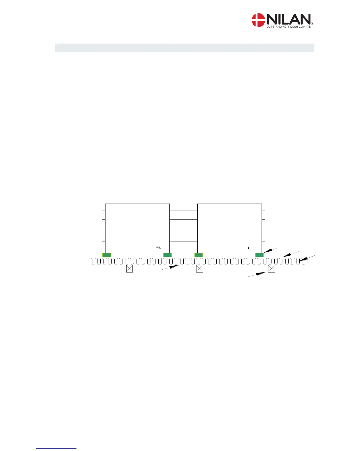
The system’s connection pieces and the pipes are connected with a flexible transition (flex
pipes/sound flex pipes or the like).
The system must be level due to the condense outlet. The condense outlet requires a clearance
height of minimum 80-105 mm under the outlet connection piece.
It is not necessary to re-insulate the system as it is delivered with a 20mm standard insulation.
The system is low-noise and low-vibration. However, potential vibrations spreading from the sys-
tem to the individual building parts must be taken into account. We recommend a minimum
distance of 30 mm from building parts and other fixtures. To detach the system from the floor, we
recommend that the system is placed on vibration absorbers as illustrated in figure 2 (See Acces-
sories)