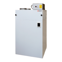
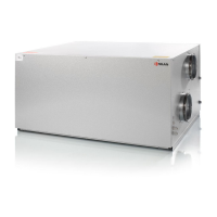
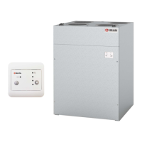
Do you have a question about the nilan Compact S Series and is the answer not in the manual?
Installation and startup must be performed by a qualified electrician.
All electrical wiring must be handled by an authorized electrician.
Connect the system strictly according to the provided wiring diagram.
Connect condensation outlet to a frost-free drain with steady decline.
Detailed list of temperature sensors and their functions.
Illustration showing the physical location of each sensor.
Condensate line must be frost-free with a steady 1 cm/m decline.
Insulate all ducting with 100mm mineral wool to prevent heat loss.
The heating element must be activated within the CTS 602 controls.
Power supply installation requires an authorized electrician.
Maintain safety distance and use fire-resistant insulation.
Heating surface includes a temperature regulator and safety thermostat.
Verify all connections and ensure the water tank is full.
Press and hold ▲/▼ and ENTER for 10 seconds.
Enable/disable inlet air heating and set regulation time.
Activate or deactivate the hot water tank's heating element.
Select Humidity, Humidity+CO2, or OFF for regulation.
Configure individual inlet and exhaust ventilation steps.
How the system operates during defrost cycles.
Set the temperature threshold to initiate defrost.
Set the temperature to stop the defrost cycle.
Choose between panel or external temperature sensors for control.
Set a minimum temperature to stop the system and prevent cooling.
Configure the minimum time the compressor stays off before restarting.
Configure the room temperature controller settings.
Settings for starting and stopping the evaporator based on heat demand.
Settings for starting and stopping the evaporator based on cool demand.
Set automatic restart for faults and fire alarms.
Reload a previously saved installation configuration.
Test various system functions manually.
Includes tests for hot water, ventilation, heating, defrost, and exhaust.
Set the Modbus address for communication with external systems.
Define the interval for data logging (1-120 minutes).
Investigate flashing alarm LEDs for fault identification.
Common causes include clogged filters, valve issues, or low airflow.
Check tank status, circulation, and water temperature settings.
Examine fuses and the hot water safety thermostat.
Clean or renew filters at least every three months.
Verify anode monitoring and connections to prevent corrosion.
| Brand | nilan |
|---|---|
| Model | Compact S Series |
| Category | Control Panel |
| Language | English |


